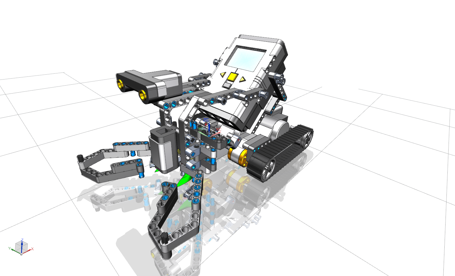
In this tutorial, you will learn how to assemble a complex assembly from individual parts.
Note that we use the following naming convention in the CAD course in assembly modeling:
The name bg_modelname_username should only be used for the entire assembly. All sub-assemblies within the overall assembly are named with ubg_modelname_username. Both the complete assembly and the sub-assemblies may contain individual parts and sub-assemblies.
Overview
In the following you get an overview of the functions covered in this tutorial:
 Assembly Navigator Assembly Navigator |
Provides an overview of the sub-assemblies and individual parts installed within the assembly. The Position column shows whether a part is fully constrained. |
 Add Component Add Component |
Inserts another part into the assembly. |
| Temporarily switches to the single part processing mode in your assembly. In this way, auxiliary geometries can be added to an individual part, which are useful for referencing, for example. | |
 Constraint Navigator Constraint Navigator |
Provides an overview of the constraints that have already been set and allows sorting according to various criteria. |
| Component Position | |
| Moves a part within the assembly by dragging it along the coordinates, if degrees of freedom are available. | |
 Show Degrees of Freedom Show Degrees of Freedom |
Displays degrees of freedom of a component. |
| Positions components in relation to others. You can choose from the following reference types: | |
|
Touch: Surfaces are joined in opposite directions. Align: Surfaces are linked in the same direction. Infer Center/Axis: Centered insertion of cylindrical elements, e.g. shaft into bore. When selecting a cylindrical or conical surface, the center or center axis of the cylindrical or conical surface is selected here. |
|
| This is used to align the axes of cylindrical elements. At the same time, the degree of freedom of rotation of both elements is fixed to each other. | |
| This "welds" two elements so that they appear as rigid bodies. | |
| Connection through an angle. | |
| Parallel arrangement of e. g. reference planes, surfaces etc. | |
| Centers one or two elements between a pair of elements. | |
| Concentric arrangement of two bodies. Note that the selected circles are on the same plane. | |
| Elements are positioned with a defined offset to each other. | |
| Position elements perpendicular to each other. | |
| Adds bodies with the same radius into each other. If the radii become unequal, the connection becomes invalid. | |
 Fix Fix |
Provides the possibility to fix a body on the current position. The first component of an assembly should always be positioned with this function (on the coordinate origin). |
| Others | |
 Perform Analysis Perform Analysis |
Starts an intersection analysis. This means that the module can be checked for existing overlaps (hard touch). |
| Overwrites the position of an assembly in a parent assembly, thus allowing movement. |
|
 Parts List Parts List |
Creates a parts list of the installed parts and allows sorting. |
