After the 11er_Balken has been installed and clearly positioned, the other components will be installed. They are NOT positioned absolutely, but referenced to the 11er_Balken.
Installation of additional parts
In the toolbar Assemblies choose Add ![]() and search for the part
steckverbinder_stange as described.
and search for the part
steckverbinder_stange as described.
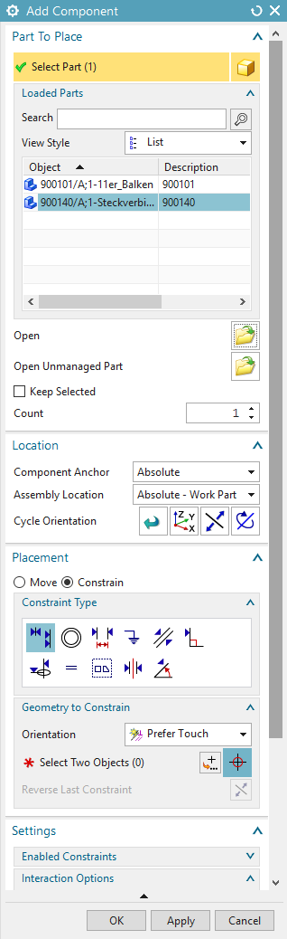
The Steckverbinder_Stange is not to be positioned absolutely, but referenced on the 11er_Balken. To do this, select the menu option "Constrain" under Placement. (Figure "Add Component Steckverbinder_Stange")
Under Type you can now select the connection conditions required for the assembly. If you need objects like centerlines, surfaces, etc. as references, that are currently obstructed by your newly added component, you can move the component by selecting "Move" under Placement and drag the coordinate system displayed in the main window. Reference objects can also be selected using the Preview Window (Figure "Component Preview").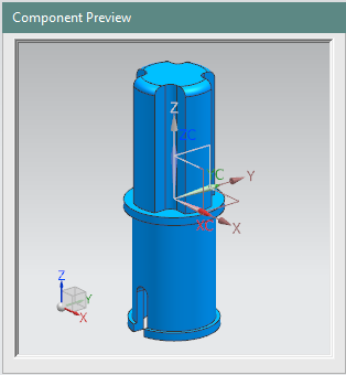
The following relationship conditions are available to you:
| Button | Name | Function |
|---|---|---|
| Touch Align |
Touch: Surfaces are joined in opposite directions. Align: Surfaces are joined in the same directions. Infer Center/Axis: Centred insertion of cylindrical elements, e. g. shaft into bore. When selecting a cylindrical or conical surface, the center axis is selected here. |
|
| |
Align/Lock | This is used to align the axes of cylindrical elements. At the same time, the degree of freedom of rotation of both elements is fixed to each other. Advantageous e. g. for inserting screws. |
| Bond | "Welding" two elements so that they appear as rigid bodies. | |
| Angle | Connection through an angle. | |
| Parallel | Parallel arrangement of e. g. datum planes, surfaces etc. | |
| Center | Centers one or two elements between a pair of elements. | |
| Concentric | Concentric arrangement of two bodies. Note that the selected circles are on the same level. | |
| Distance | Position elements with a defined offset to each other. | |
| Perpendicular | Position elements perpendicular to each other. | |
| Fit | Adds bodies with the same radius into each other. If the radii become unequal, the connection becomes invalid. | |
| Fix | Provides the possibility to fix a body on the current position. |
Difference between Touch Align and Concentric:
Although not immediately obvious, the two functions differ considerably. With both
functions, cylinders can be positioned on the same central axis. The difference is that
with Concentric, the selected cylinder edges are placed firmly on a plane and an
error message appears when the edges are moved (Figure
"Difference "Touch Align" (left) and "Concentric"
(right)"). In order to arrange two cylinders on the same axis but with a
distance to each other, we recommend the following procedure: The cylinder axes are to
be placed on top of each other with Touch Align and the selection Align
under Orientation. Now you can use the "Distance" function to
define the relative displacement.
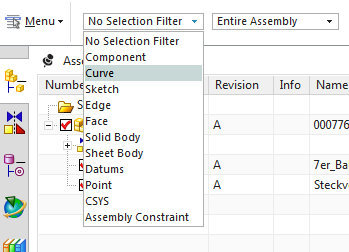
With the Filter function ![]() you
can select specific elements, since all other types are no longer selectable. The Filter
function can be found in the upper left corner of the start menu. (Figure "Filter")
you
can select specific elements, since all other types are no longer selectable. The Filter
function can be found in the upper left corner of the start menu. (Figure "Filter")
Furthermore, there is also the possibility to move parts by means of the Move
function based on their still open degrees of freedom. To do this, you must
leave the window in which you assign the assembly constraints and right-click on the
desired part. Now select Move![]() . Moving works in the same way as moving the WCS. You have
several options for terminating the function:
. Moving works in the same way as moving the WCS. You have
several options for terminating the function:
- OK: The menu closes and the part remains in the position you have moved it to.
- Apply: The part also stays in the new position, but the menu remains open and the part is deselected so that a new part can be selected and moved.
- Cancel: The menu is closed and the part is reset to its original position, the movement is not carried out.
You can also right-click on the part in the Part Navigator or in the model to select
Show Degrees of Freedom .
The still open degrees of freedom of movement are now displayed as red arrows. This
information is used to change the position of the part or to set missing assembly
constraints. After you have set an assembly constraint, press F5 to update
the open degrees of freedom view and remove the red arrows.
.
The still open degrees of freedom of movement are now displayed as red arrows. This
information is used to change the position of the part or to set missing assembly
constraints. After you have set an assembly constraint, press F5 to update
the open degrees of freedom view and remove the red arrows.
- Select the link condition.
- In Component Preview, choose your required element (for example, area, plane, axis, and so on).
- In your model, select the element you require (e. g. surface, plane, axis, etc.).
- Repeat the procedure until all degrees of freedom have been taken into account..
- Confirm with OK.
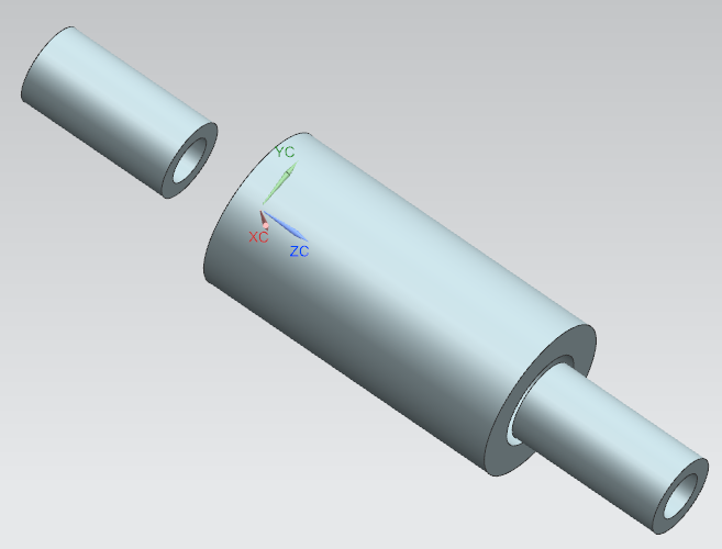
To reference steckverbinder_stange to the 11er_Balken, you can use the
Infer Center/Axis linking condition. Select the surface of the cylindrical end of
the Steckverbinder_Stange and then select the surface of the hole in the
11er_Balken. To restrict the remaining degrees of freedom (rotation around the
center axis and translation along the center axis), it is advisable to use the
connection conditions Touch and Parallel.
If you have closed the Add Component window too early and
the part is not fully aligned, you can add more relationship conditions later. To do
this, click on the part to be referenced with the RMB. In the context menu that
now opens, click on Assembly Constraints and proceed as usual with
alignment.
and proceed as usual with
alignment.
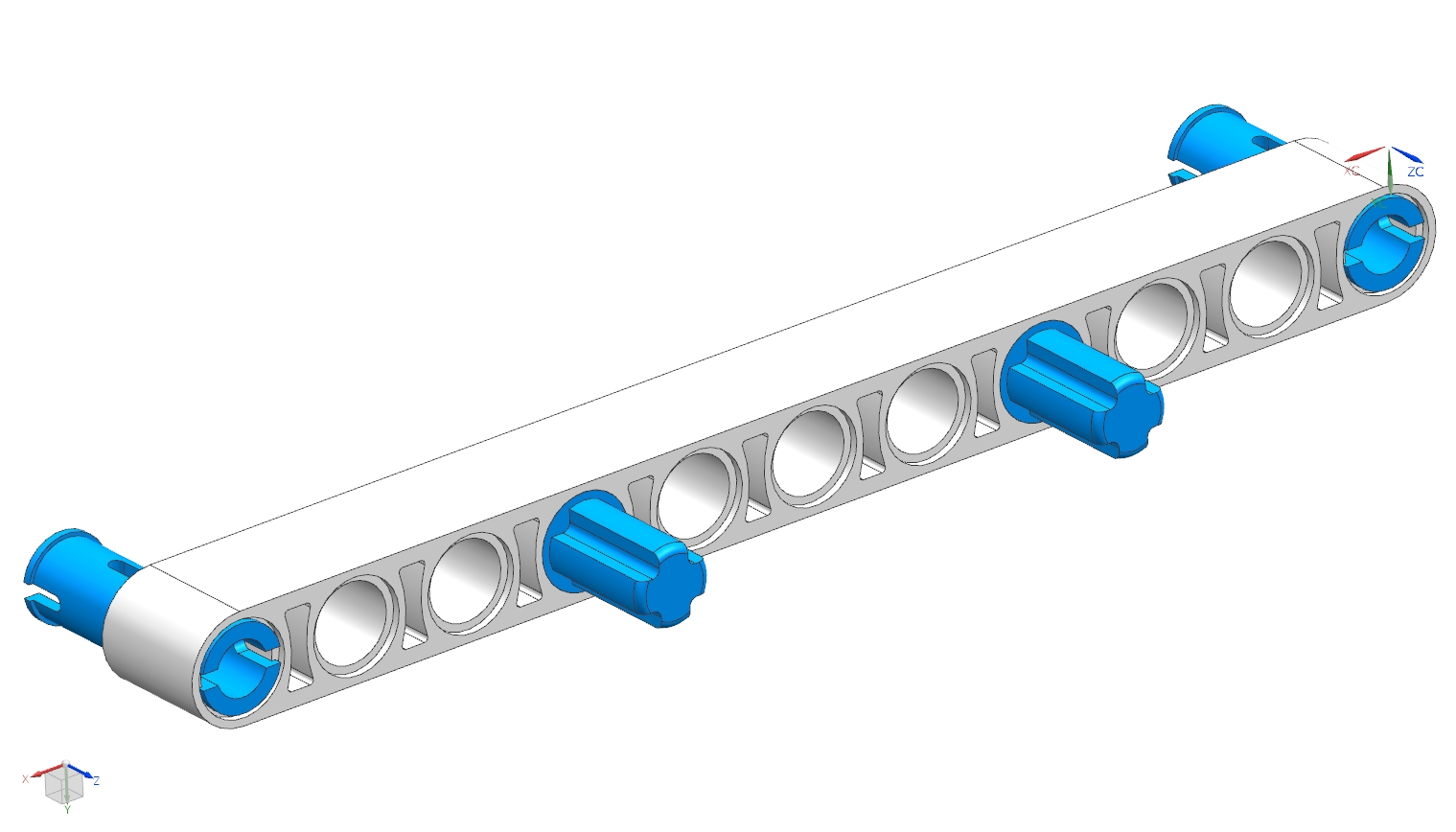
Now install the remaining parts and the subassembly ubg_sensor_tast with the now known functions. Please refer to the pictures:
- Steckverbinder (2x) and Steckverbinder_Stange (2x) Figure "Interim Status 1"
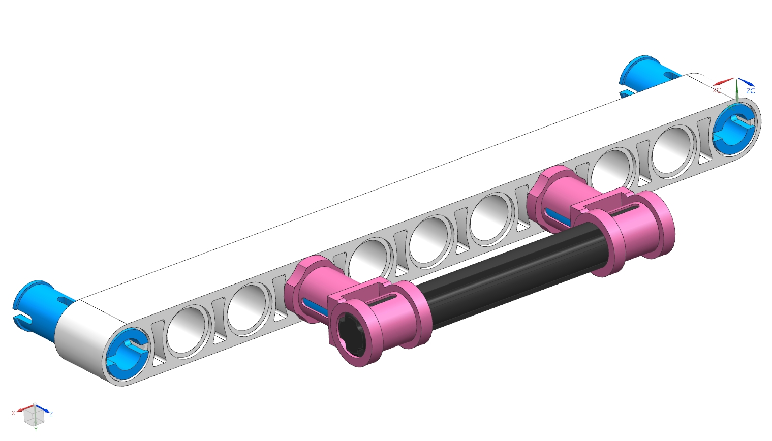
- Stangen_Querverbinder (2x) and 5er_Stange Figure "Interim Status 2"
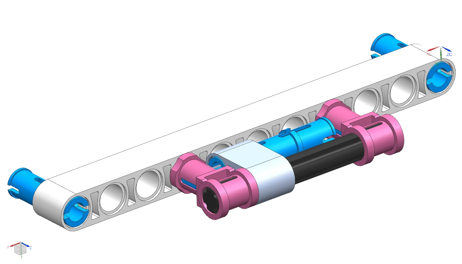
- Parallelsteckverbindung and Steckverbinder_lang Figure "Interim Status 3"
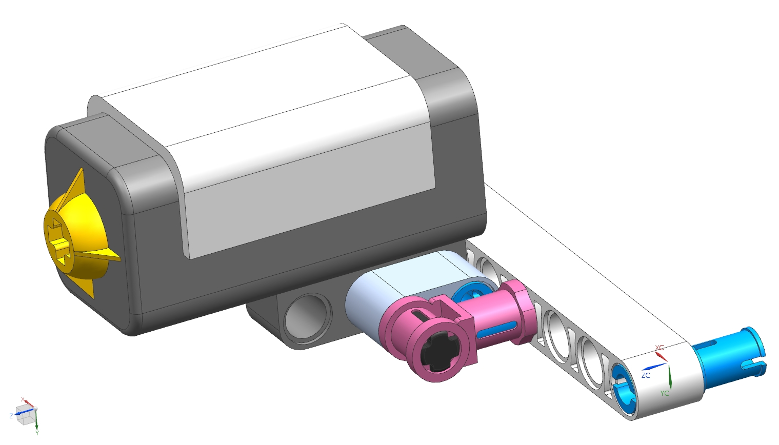
- Parallelsteckverbindung and UBG_Sensor_tast Figure "UBG_Sensor_hinten_gesamt".
| Note: |
|