Deriving the drawing with the Creation Wizard
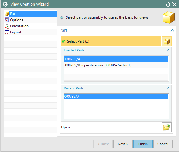
After entering drawing mode, NX will now automatically open the View Creation Wizard (see figure "View Creation Wizard") to help you create the part drawing. In four steps, you can make and adjust the basic settings for the drawing.
| Note: |
|
You will now be guided through the following menu items:
- Part: If you have opened an assembly, you can select here whether an individual part or the entire assembly is to be displayed in the drawing.
- Options: Make sure that drawings are to be drawn up in standard
scales. Check the scale that NX automatically selects. If this is not
standard-compliant, set "View Boundary" to Manual,
uncheck "Auto-Scale to Fit" and select a standard scale from the drop-down
menu (we have chosen "5:1" in our example). To show hidden lines,
select -------- under "Process Hidden Lines" in
the drop-down menu instead of Invisible and in the second
field ——— 0.25 mm instead of Original. You may need to check the "Process Hidden
Lines" option. You can also select whether to display centerlines or not. Under
Preview Style, you can determine how your item or assembly is displayed in the preview.
It is a good idea to select Hidden Wireframe
 to get a
realistic preview of the positioning.
to get a
realistic preview of the positioning. - Orientation: Here you can select the basic view. In this example we have chosen "Top".
- Layout: To specify all dimensions of an individual part or assembly, it is
usually necessary to display multiple views. Here you can select which views are
displayed on the drawing. Create another projected view of the left side by selecting
"Left"
 . The arrangement is automatic.
The distribution on the drawing sheet is displayed in the preview. If you want to change
the arrangement manually, select "Manual" instead of "Automatic"
under Placement.
. The arrangement is automatic.
The distribution on the drawing sheet is displayed in the preview. If you want to change
the arrangement manually, select "Manual" instead of "Automatic"
under Placement.
When you have made all the settings, close the window with a click on Finish.
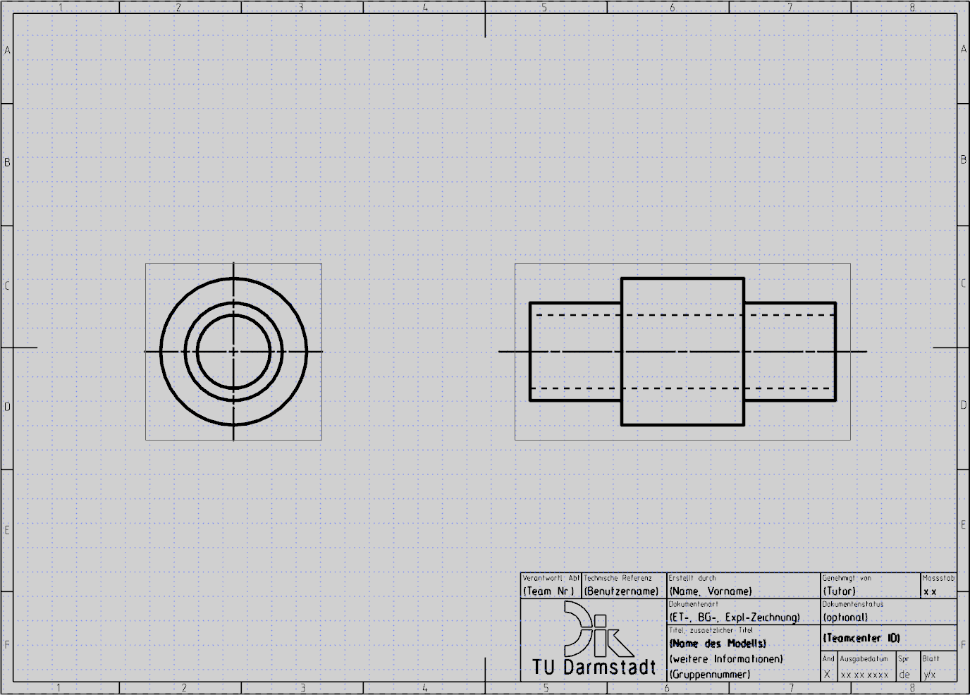
Your drawing should now look like the one shown in the illustration (see figure "View from
left").
If you want to edit or replace the views, this cannot be done via the wizard. In this case,
proceed as described in the section "Manual
Derivation of Drawing" (see below).
Manual Derivation of Drawing
Compared to the View Creation Wizard, manually deriving a drawing in NX offers more design freedom. To derive a drawing manually, proceed as follows.
Deriving the Base View
Close the View Creation Wizard without creating a drawing and open the Base View menu by choosing Insert -> View -> Base. NX is now in the mode for creating the basic view. It offers you different options for the views and the scale, as well as a preview of the current view of the part.
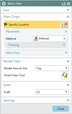
Figure (see figure "Base View") shows the ribbon Base View, which is structured as follows:
- Part: To select another part
- View Origin: Adjustment possibilities via the placement of the component
- Model View: Top, Bottom, Front, Back, Left, Right
- Scale: Scale setting
- Settings: Changing the drawing settings
There are two ways to derive the basic view:
- You choose Orient View Tool
 .
Here you have the possibility to freely define your view with the help of dynamic
rotation, vector constructor functions and WCS functions.
.
Here you have the possibility to freely define your view with the help of dynamic
rotation, vector constructor functions and WCS functions. - You select one of the predefined views (Top, Bottom, Front, Back, Left, Right).
Then select the correct scale and place the basic view with LMB on the left side of the drawing surface. In this example, the "Top" view and the 5:1 scale are used.
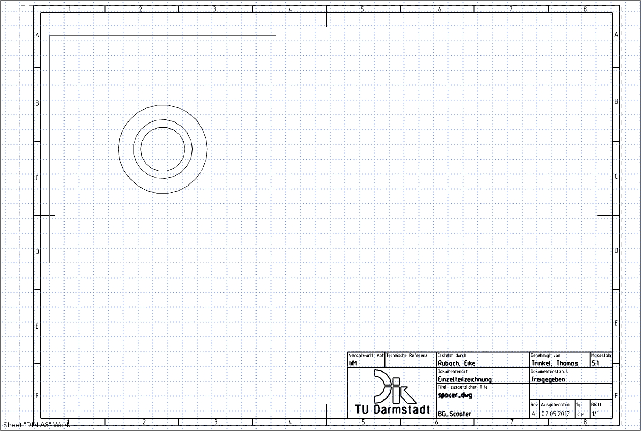
Your drawing should now look like the figure "base view derived". (figure "Base view derived")
|
Note: |
|
Deriving the Projected View
After you have placed the base view, NX switches to the mode for projected views and the Projected View window appears.
| Note: |
|

Now you can derive further views of the component according to the projection rule.
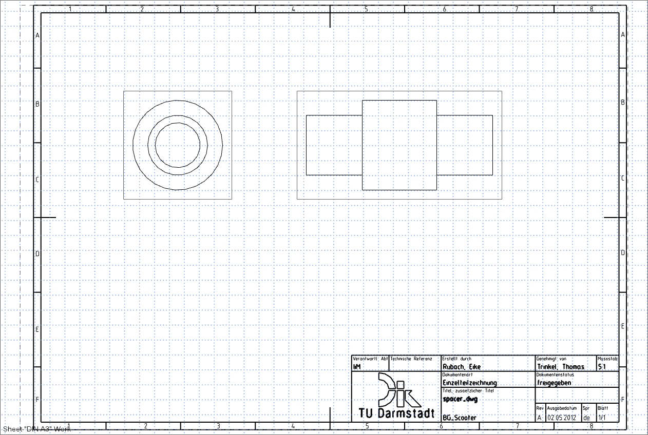
For the second view, project it to the right so that you get an orthogonal view from the left. Your drawing should now look like the following figure (see figure "View from left").
Press the Esc key or the middle mouse button on a free area to abort the process.
| Note: |
|
Other functions
Hide Frame
If you want to hide the frames around the individual views, proceed as follows:
Preferences -> Drafting. Now select the tab View in the Drafting Preferenced menu and select the submenu Workflow.
Remove the check mark under Border in front of the option: Display
Adjust frame
If the frame should cut off your drawing, it is possible to adjust it automatically.
To do this, right-click on the frame of the view and select Boundary.
In the Drop-Down-List, change the entry to Automatic Rectangle
and confirm the selection with OK.
The red Anchor Point doesn't need to be taken
into account.
Hide Grid
If you want to hide the grid, proceed as follows:
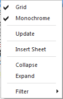
In the Part Navigator, use the RMB to click Drawing and deselect the option Grid. (see figure "Hide Grid")
Delete Views
To delete individual views, you must select them by clicking the frame with the LMB and then select Delete or press the Entf key.
Derive a new view
If you want to derive a new or another projected view from an existing base view, select the base view and then click Projected View
When you derive the views, NX automatically generates the centerlines.
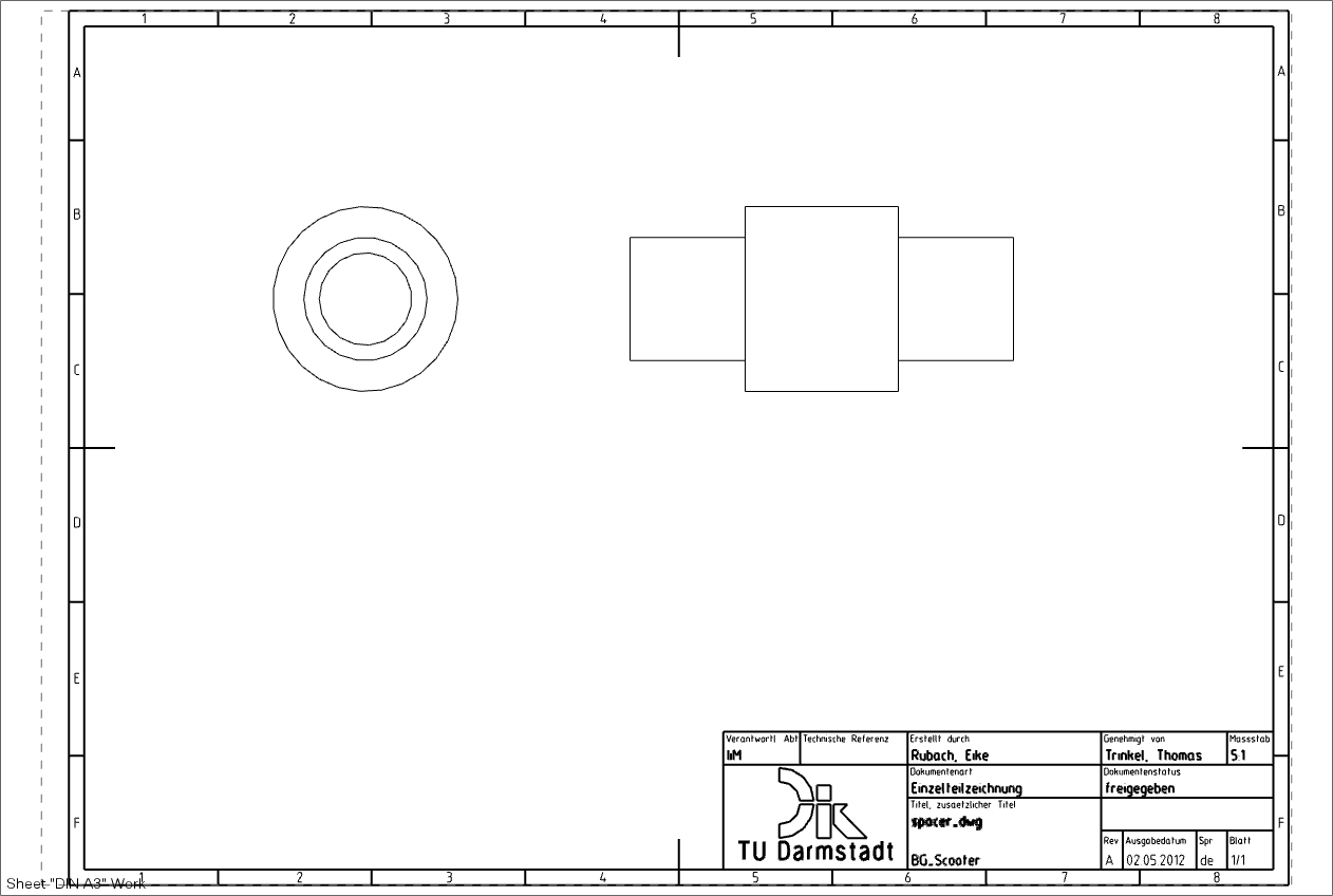
You can delete them by clicking  . (see figure "View without Grid, Frame and
Centerline ")
. (see figure "View without Grid, Frame and
Centerline ")
Change view name
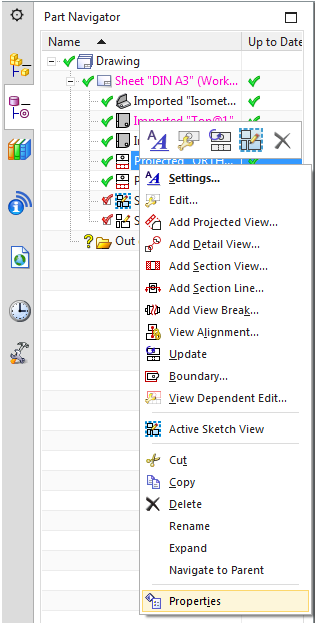
After a right click on the desired view in the Part Navigator, the menu item
Properties can be selected. (see figure "Derived View in Part Navigator")
Here you can change the view name in the Name input field of the
General tab page, in e. g:
- Basic view
- Side view
- Sectional view
- Detail view
- etc.
This will make it easier for you to assign the view names to the views later on if you have
several views in a drawing.