In this tutorial you will learn how to display section views in accordance with the
standards.
For this you need the drawing ubg_rolle_schnitt_dwg and the
corresponding master model.
Hiding hatching
NX cuts the complete part or assembly when creating section views. However, not every component may be sectioned for a standard representation, so some hatches have to be hidden again.
The following components may not be sectioned for a standard-compliant representation:
- Standard parts
- Rotationally symmetrical components (shafts, axes and spheres)
In this section, the rotationally symmetric parts axis and axle bolting are located, the hatching of which is to be hidden.
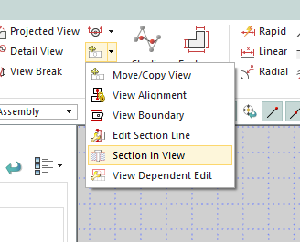
- To hide the hatching, choose Section in View
 . (see figure "Section in View in the bar")
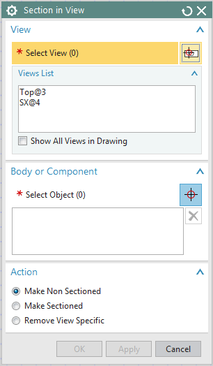
 The Section in View window opens. (see figure "Section in View Menu")
- First select the section view in which you want to hide component hatchings. In this case, select the only available section view.
Under Body or Component, the components must now be selected. To do this, you can select the axis (achse_vorn) and the axle bolting (achsschraube) directly in the drawing. This is often very difficult, because the components are close to each other and therefore a specific selection is impossible. It is advisable to select the objects in the Assembly Navigator
- Select the parts in the Assembly Navigator. To select multiple objects, use the key Strg.
- Under Action select Make Non-Sectioned. This setting cancels the section.
- Confirm with OK .
- If necessary, you may have to update the view again with Update Views
 .
.
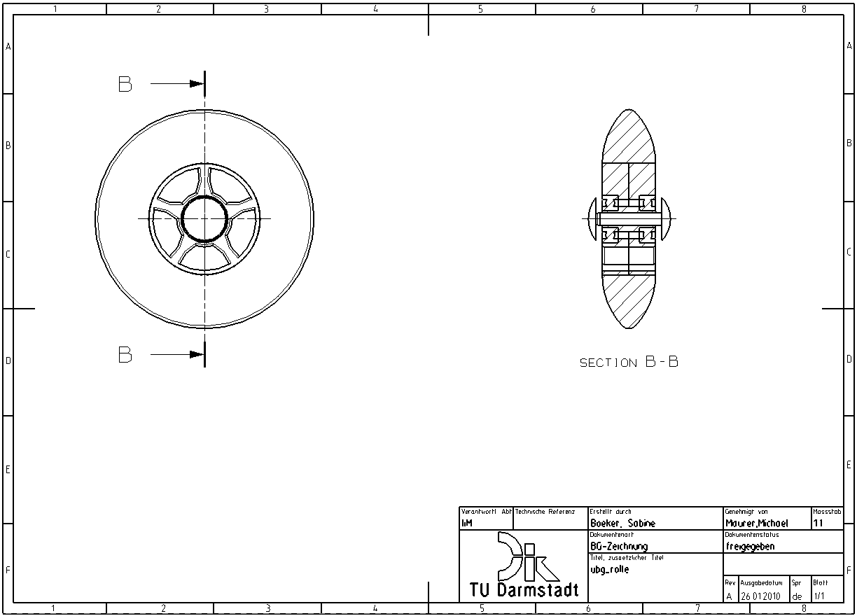
Your drawing should now look like in (see figure "Hidden hatching").
| Note: |
|
Assembly hatching
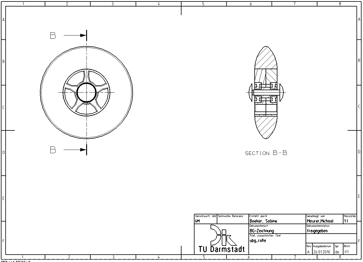
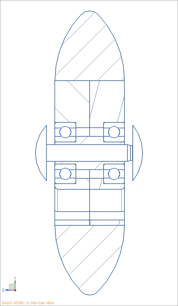
In order to be able to distinguish between different parts within a sectional view, they have to be hatched with different orientations. If your hatching consists only of parallel strokes (see figure "Hatching"), proceed as follows:
Choose Edit Settings ![]() .
.
- Select the section view and confirm with OK.
- Under Section->Settings activate Display Assembly
Crosshatch and Restrict Crosshatch to +/- 45
Degrees.
- Confirm with OK.
| Note: |
|
Modifying hatching manually
When hatching assemblies in NX, the hatching distance is not adapted to the component size.
In the following sections, the hatching distance and pattern are adapted to the material. You should switch to the "Work in Member View mode":
- Click with the RMB on the frame of the section view in the drawing of the ubg_rolle.
- Then click Expand. (siehe Abbildung "Section view in Work in Member")
To change the hatching, proceed as follows:
- Open the menu for editing hatches via Edit Settings
 .
. - Select the roll hatch pattern and confirm with OK.
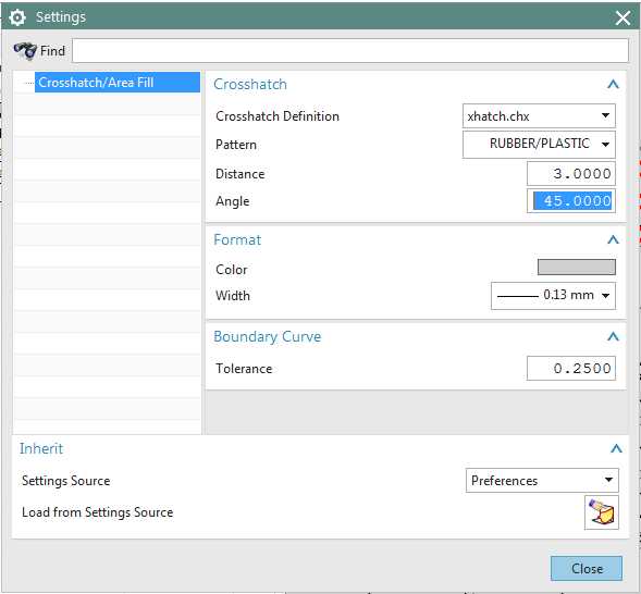
The Settings window appears.
Adjusting hatch spacing
To change the hatching distance to 3mm, enter 3 in the Distance field and confirm with Enter..
Adjusting the hatching to the material
The roller is made of rubber. Plastics are cross-hatched in accordance with
the DIN ISO 128-50 standard.
The default hatchings for the
most common materials can be selected directly from
the Pattern drop-down menu.
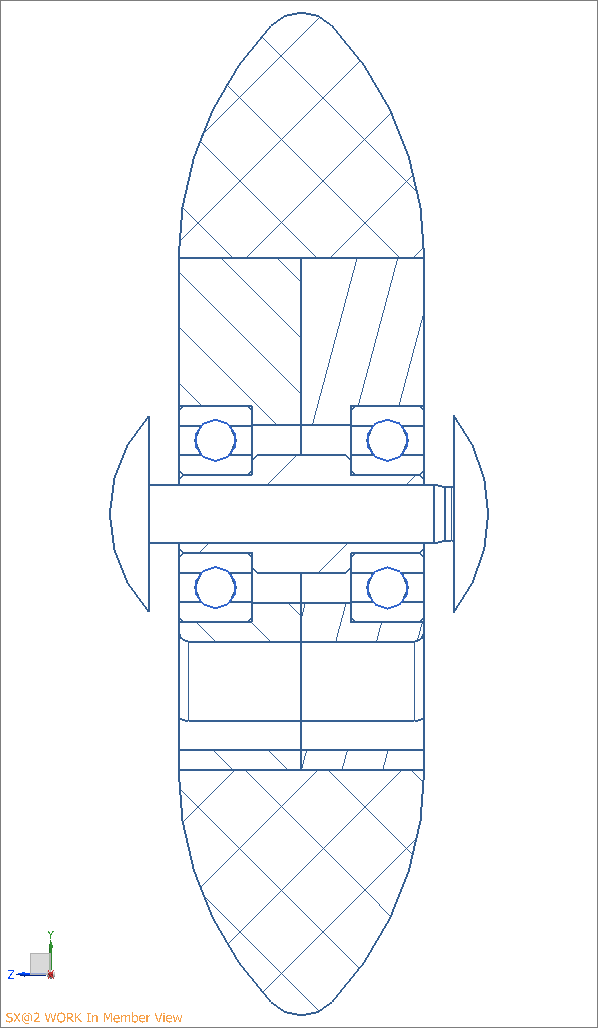
Exit the Work in Member View by clicking next to the view, right-clicking the pull-down menu and unchecking Expand.
Your section view should now look as shown in the figure (see figure "Crosshatch"). This drawing has standard hatching, but the bearings, for example, are not yet shown correctly. A detailed treatment of the standardized representation of the machine elements exceeds the range of this course. Please refer to further lectures.
You should always check whether the hatching angles are 45° or
135°. Adjust the remaining hatch spacing to your part sizes by repeating the process for
all cut elements.