For the sake of completeness, you will insert the main and connecting dimensions into the assembly drawing in this exercise unit.
To do this, you need the specification ubg_rolle_schnitt_dwg, which you created in the previous exercise section.
To do this, you need the specification ubg_rolle_schnitt_dwg, which you created in the previous exercise section.
The complete assembly drawing includes the insertion of main and connection dimensions.
Hide the following models in the Assembly Navigator  :
:
- kugellager (2x)
- spacer
- achse_vorne
- achsschraube
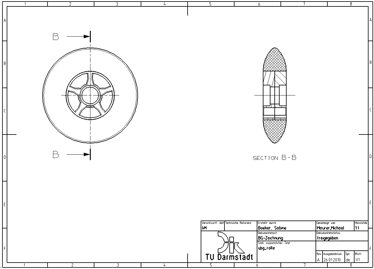
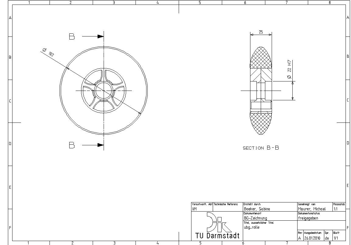
After you have updated your drawing, it should look as shown in figure (see figure "Rolle with hidden models"). In the side view, insert the main dimensions and connection dimensions. In this drawing these are:
- Diameter of the Rolle
- Width of the Rolle
- Diameter of the standard holes into which the bearings are later joined
Complete your assembly drawing according to the figure (see figure "Main and connection dimensions").
| Note: |
|