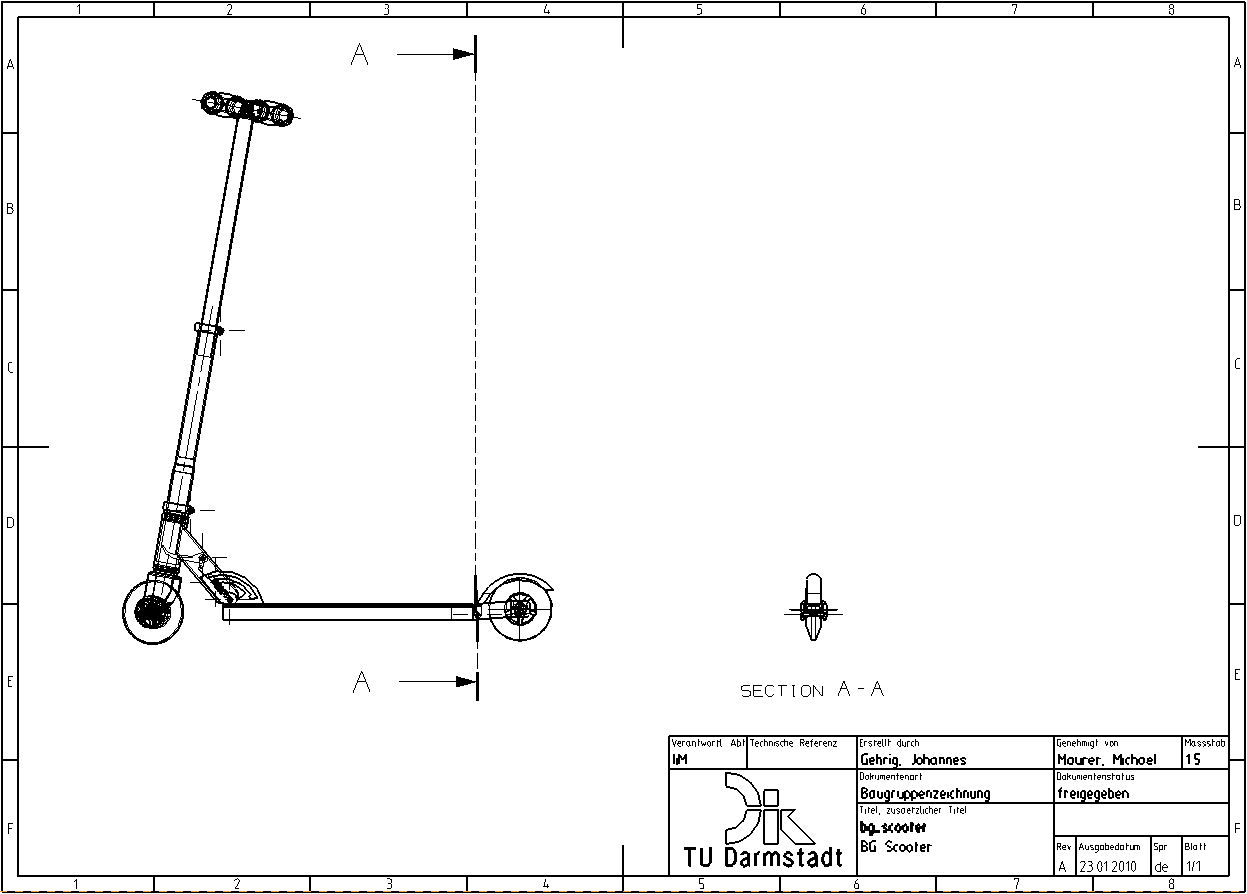
To do this, you need the just created specification of the bg_scooter assembly.
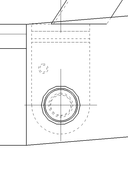
An offset bore hole can now be seen on the mounting of the rear wheel (see figure "Drill hole"), which can be made visible by a step cut. Step cut is an extended function of the simple cut. Proceed as follows:
- Start with Section View
 .
. - As Method, select
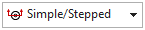 .
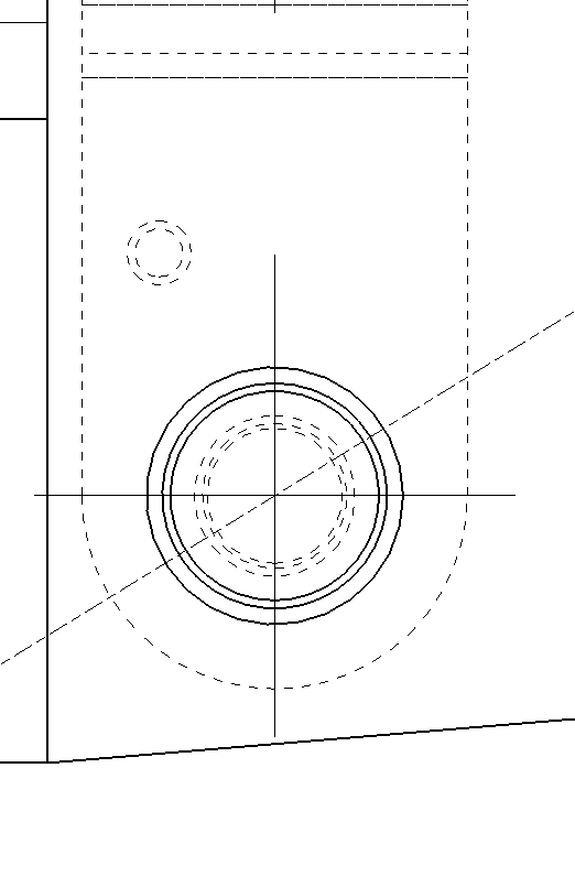
. - Under Section Line Segments click Specify Location and first select the center of the first hole (see figure "first center") and then, after clicking Specify Location again, select the center of the smaller, concealed hole (see figure "second center").
- A stepped intersection line is created through the two hole centers.
- Pay attention to the correct viewing direction of the cut (possibly change with
 ).
). - Now click on Specify Location under Orientation and position the view according to the illustration (see figure "Positioning the section view").(see figure "Positioning the section view").
| Note: |
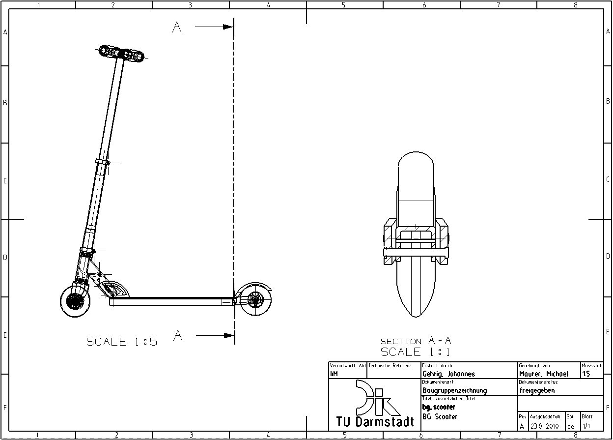
Your section view will contain two springs that should not be displayed in this view. With RMB -> Hide on the respective spring you can hide it. |
If you want to edit your section at a later time, e. g. add/delete/move a stage, you can open the Section View window again by double-clicking on the intersection line. Now you can click and drag to move existing points or create a new point. By right-clicking on an existing point you can delete it with Delete.
Change scale
To change or display the scale of a view, double-click the view frame to open the Settings window.
Under Common -> General -> Settings -> Scale you can set the desired scale.
Under Common -> Section -> Label -> Scale you can use Show View Scale to display the section scale.
The following corrections must now be made to the drawing:
- Delete the hatching of parts that must not be cut.
- If necessary, adjust the other hatchings.
- Change the scale to 1:1.
- Show the scale in the drawing.