This chapter is focused on technical product documentation. In the course of the exercise, you will create a technical drawing of an individual part and an exploded view of an assembly.
Basics
A technical drawing is a means of communication that provides clear information exchange in different application areas. Therefore, the derivation of 2D drawings is still an important step in the age of 3D CAD technology.
When creating a drawing, it is always important to ensure that all functions and properties of the 3D model are recognizable and unambiguous. Accordingly, the creation of drawings in accordance with standards can be a time-consuming and tedious task. This applies in particular to complex geometries or assemblies. Nevertheless, the correct and conscientious preparation of the drawing is essential, as the properties of the product not contained in the drawing may not be realized! Even an incorrectly entered fit or a missing surface specification can ruin the entire development work, since the product does not function at all or only to a limited extent later on.
Master-Model Concept
In principle, it would be possible to derive a drawing directly from a component. This directly derived drawing would correspond to the state of completion of the model at the time of its creation. If the part is developed further, the drawing will not be adapted. In NX, a drawing derived directly from the drawing is called "stand-alone drawing".
However, since a project cannot be carried out step-by-step during the product development process, but the development steps are carried out in parallel, the component must be easy to modify in each phase. Therefore, the master model concept is often used in CAD systems. The basic model for a specific development step is referenced in a new file as a so-called master model. The technical drawing is then derived from this master model. This means that the respective part can still be changed while changes in the drawing do not affect the model.
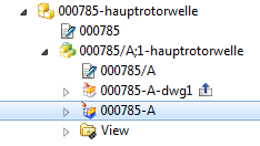
In Teamcenter, the drawing is added to the current item revision as a "specification" (see figure "Specification in Teamcenter").
Overview
Here you get an overview of the functions covered in the tutorial:
| View (Drawing) | |
| Derives the drawing with the Creation Wizard. | |
| Creates a basic view. | |
| Creates projected views from the basic view according to the projection rule. | |
 Detail View Detail View |
Creates an enlarged detail view from an existing view. |
 Section View Section View |
Inserts a section view. You can choose between simple (simple/stepped) half or revolved section view. |
 Break-out Section View Break-out Section View |
Creates a cut-out that can be used, for example, to uncover a blind hole. First, a boundary curve must be created in Active Sketch View using the Studio Spline function. |
 Section in View Section in View |
Shows or hides hatching. |
 Update Views Update Views |
Updating derived views after changes to the master model. |
| Dimension | |
 Linear Linear |
Adds a linear dimensioning, where you can choose between horizontal, vertical, parallel, vertical or cylinder dimensioning. |
| |
Adds a standard radius or diameter dimension. |
| NX automatically selects a suitable dimensioning method. | |
 Angular Angular |
Adding an angular dimension. |
 Chamfer Chamfer |
Add a chamfer dimensioning. |
 Thickness Thickness |
Add a circular thickness dimensioning. |
 Arc Length Arc Length |
Adds a circular arc dimension. |
 Ordinate Ordinate |
Adds a coordinate dimension. This tool is also suitable for creating a progressive dimension. |
| Sonstiges | |
| Adds a view boundary. | |
| Add or change the dimension text by clicking on the respective dimensional value. | |
| |
Adds a text note, e. g. for specifying a standard. |
| Explosion | |
| Adds a new exploded view. | |
 Auto Explosion Auto Explosion |
Inserts an automatic exploded view after a predefined distance. |
 Edit Explosion Edit Explosion |
Moves the components within an exploded-view drawing. |