Now the approach of remodeling simple blocks will be introduced. As an example, a 3D-Model will be provided. This however is neither parametrized, nor has it any used features saved in the Assembly Navigator. The only possibility to get the measurements of the block is measuring the example block.
A similar task will be expected in the first examination phase (PA1).
Instruction on the remodeling of unparameterized blocks
The following aspects are to be attended during the remodeling of the unparameterized blocks during the weekly exercises as well as the examination phases:
- To measure the elements of design, e.g. angular holes, it might be necessary to design reference elements.
- Every Feature was designed with values that have at most one decimal place. Exceptions are values ending on x.25 or x.75. Angled faces can either be designed using angles or linear measures. While remodeling, adhere to the even values.
- Use the standard angle of 118° for blind holes.
- Use the learnt design strategies (e.g. large to small elements)
- To check the results it is necessary to orient your block in the same way the unparameterized block is oriented in the absolute coordinate system.
Changing in between the windows
Opening the example block and the remodeled block parallel in NX will simplify the task. You can switch between Windows by clicking Window in the uppermost bar and selecting the relevant window. You can distinguish the windows by their part number.
Relocating geometries relatively to the absolute coordinate system
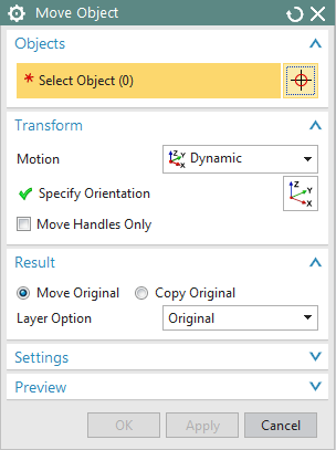
To be able to compare your block with the example block, it is important that the coordinate systems of both blocks are oriented equally. If you ignored this at the beginning of your construction, you can later relocate your block to the absolute zero by using the option Move Object ![]() (Edit-> Move -> Object) (see fig:"Move Object").
(Edit-> Move -> Object) (see fig:"Move Object").
Creating and working with reference points
To create reference points use Insert -> Datum/Point -> Point. You could use these Points for example to create Datum planes.
Note possible differences between your absolute coordinate system and the WCS.
To choose points, select them in the main window or in the Part Navigator.
If you wish to hide a point, use Edit -> Show and Hide -> Hide.
Edit -> Show and Hide -> Show gives you the possibility to deactivate the hiding function. This option is also available in the context menu, which is opened by clicking the right mouse butten (RMB) on the entry of the point in the Part Navigator.
Use this procedure only for the analysis.