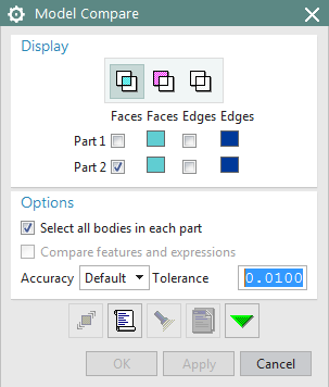
The Model Compare function allows you to compare two geometries with each other. NX places the geometries, oriented to the absolute coordinate system, on top of each other. Differences in color indicate whether and where there are differences between the two bodies.
Open the Model Compare ![]() function via Analysis -> Model Compare.
function via Analysis -> Model Compare.
Leave the default settings unchanged. (see figure "Model Compare")
First click on the geometry in the work window and it will be highlighted in color. Then switch to the second geometry via Window and select it as well.
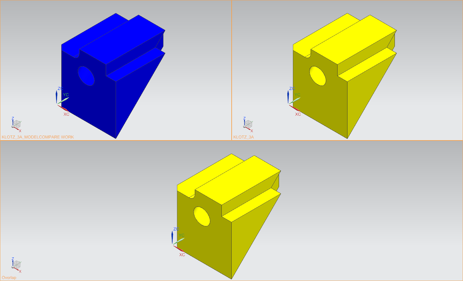
The Model Compare work window opens automatically. (see figure "Model Compare before "Apply"")
The first geometry is located in the three-part work window at the top left, the second one at the top right. Below you can see the comparison of the two in which the geometries are superimposed.
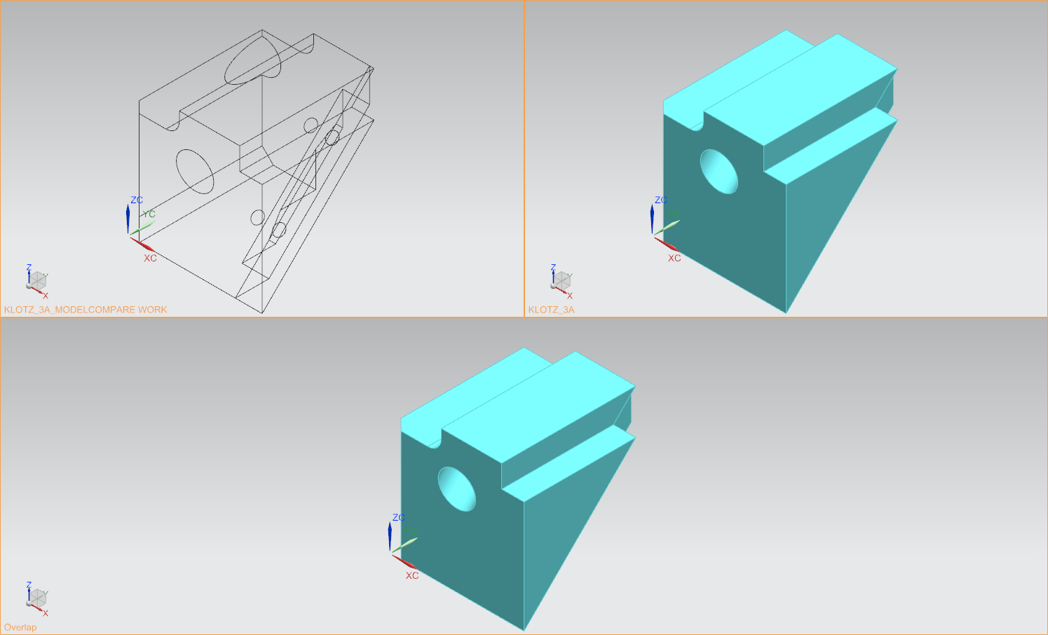
Next, click Apply in the Model Compare window. The appearance of the geometries in the three-part window then changes so that errors become visible. Before clicking on Apply, the geometries had the colors they also have as items. After the application, they are only shown in the edge display or colored light blue, according to the standard settings. If both geometries are identical, your working window corresponds to the following figure. (see figure "Model Compare after "Apply"")
By clicking with the RMB in one of the three sub-windows, you can change the display form (wireframe, shaded,...). In addition, all three geometries can be rotated independently of each other by clicking into the subwindow with the CMB and holding it down to rotate.
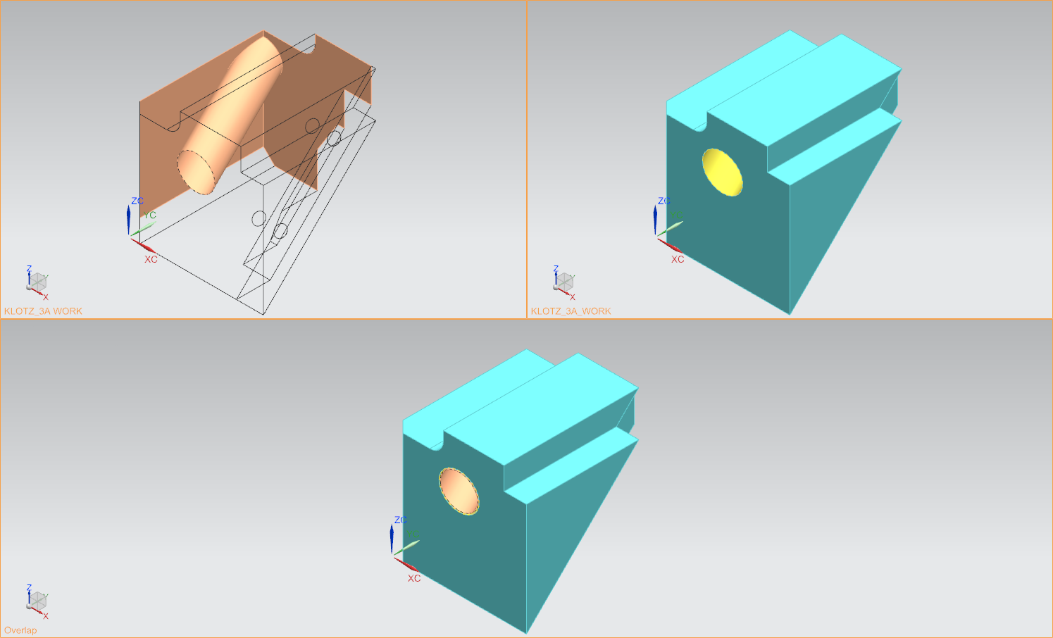
If the two geometries are not identical, colour deviations occur at the points where the material is left over when comparing the bodies. In the illustration (see figure "Display of faulty geometry"), the hole in the upper left-hand part of the window was set one millimetre too far to the right.
This will highlight the hole in color in all three views. Note that the adjoining rear side faces are also marked, as their dimensions are also incorrect due to the incorrect position of the hole. By default, the body is shown in the upper left corner is visualized as a wireframe with highlighted errors in beige. In the upper right corner of the body the defects are shown in yellow and in the reference body a mixture of yellow and beige is shown.
To exit Model Compare mode, click Cancel in the Model Compare input window.
| Note: |
In order to compare two geometries, it is necessary that both geometries are oriented to the absolute coordinate system in the same way. If you did not take this into account at the beginning of your design, start the Model Compare procedure as described above. However, before you execute the function with Apply , you must move one of the geometries using the Reposition Bodies
In practice, a combination of both methods has proven its worth. First use dynamic positioning to move the body close to the desired position and then use the procedure described in the second point to position the bodies exactly. |
 function. Once you have clicked on Reposition Bodies