To create an explosion drawing, proceed as follows:
- Open the assembly ubg_rolle_tpd.
- Create a new drawing according to the naming convention and select the drawing frame A3 - DiK - Stückliste (Set no default view). Leave the View Creation Wizard that now appears open.
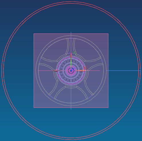
- Switch to modeling mode (see figure "Modeling Mode") and make sure that the Assemblies option is enabled in the File menu.
Select the Assemblies tab in the toolbar. The following functions are available under Exploded Views![]() .
.
- Click New Explosion
 to create a new view for the exploded view.
 - Name them clearly.
- Use Auto Explode Components
 to automatically unplug the components. After you have pre-defined a distance, they are all pulled apart by the same distance. Determine whether this makes sense for your drawing.
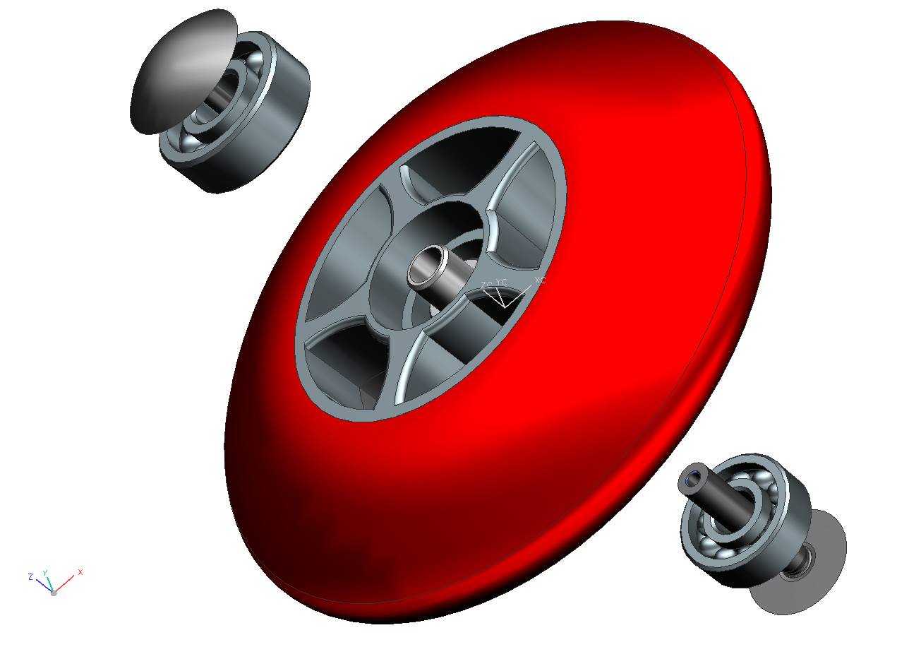
In the first step you can simply select everything. The distance you enter indicates how far the components are moved outwards.(see figure "Auto Explosion")
| Note: |
|
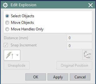
To edit the exploded view manually, choose Edit Explosion![]() (see figure "Edit Explosion"). If you have accidentally clicked on Move Component
(see figure "Edit Explosion"). If you have accidentally clicked on Move Component![]() , the following dialog box will take you to the same functionality by clicking on Edit Explosion.
, the following dialog box will take you to the same functionality by clicking on Edit Explosion.
If possible, the individual parts should be moved along an axis.
- Select Select Objects and then select the component you want to move.
- Then click on Move Objects. A coordinate system appears.
- You have two options for moving:
- Click on the axis of the direction in which you want to move the component and enter a value.
- Click on the axis of the direction in which you want to move the component and drag it with the mouse to the desired position.
- Click Select Objects again and repeat the procedure with another component (make sure that your previous component is not selected -> Shift key).
 Manually edited
| Note: |
|
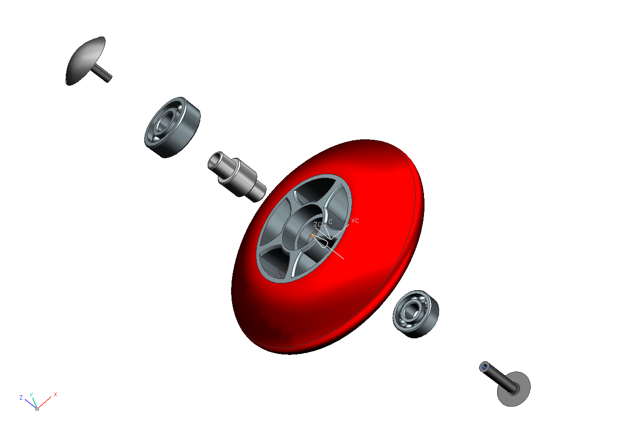
If you are satisfied with the presentation, save the view via View -> Operation -> Save As... under the name Explosion (refer figure "Manually edited").
| Note: |
|