To do this, you need the specification of the role with its exploded view, the parts list frame A3 - DiK - Stückliste and the corresponding master model.
The labeling field is created according to the standard: DIN EN ISO 7200.
Bills of material are drawn up in accordance with the standard DIN 6771-2.
In the exercises and the Prüfungsabschnitt 3 (PA3), the principle of the parts list in the main drawing is used.
The row with the column header is located directly at the header field and the numbering is done from bottom to top.

Open the specification created in the previous chapter and switch back to drawing mode. With the View Creation Wizard, which is still open, you can insert the exploded view into your drawing frame. Under Select Part , make sure to select the specification in which you created the exploded view.
The drawing frame contains a prefabricated parts list which is not yet filled in when opening. To fill in the list automatically, select the complete parts list by clicking with the LMB in the upper left-hand corner of the parts list. Then click on Update Parts List (see figure "Automatic parts list").
Insert view and assign item numbers
Insert the exploded view as the basic view. Use Base View ![]() .
.
To do this, select the view Explosion you created previously under Model View to Use.
Note that under Parts, the specification in which you saved the exploded view is selected.
Now the list entries must still be assigned to the individual parts. This is done using item numbers. Click on Autoballoon![]() and then on the parts list. Confirm with OK. The item numbers are now assigned automatically.
and then on the parts list. Confirm with OK. The item numbers are now assigned automatically.
In accordance with DIN ISO 6433, the following notes must be observed when inserting item numbers:
- Each item number must be connected to the corresponding part via a reference line. The reference lines are entered into the drawing at any angle (not horizontal or vertical).
- Leader lines must not cross and should be as short as possible.
- Leader lines should not intersect with components.
- The reference arrows end on the outer boundary line of the component (not in free space and not within the component).
- Position numbers should be arranged vertically one below the other and/or in horizontal rows.
- Item numbers of identical parts only need to be entered once if this is clearly stated.
Further information can be found in DIN ISO 6433.
| Note: | It is possible that not all components are assigned the corresponding item number. Check for completeness (see figure "Auto Balloon"). |
Insert item numbers manually
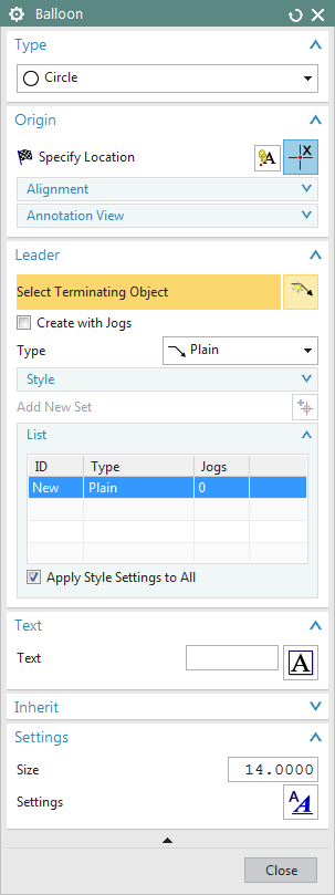
Select Balloon![]() . A dialog box appears. (siehe Abbildung "Balloon")
. A dialog box appears. (siehe Abbildung "Balloon")
- Enter the required item number in the Text input window.
- Activate the check mark in front of Create with Jogs under Leader and click on a body edge of the object to which the position number should point. The position number is now generated anywhere.
- To position the item number, click on Specify Location (top of the window) and position it.
- Exit the context menu with Close.
The remaining buttons can be used to optically modify the position numbers.
Append additional arrows to position numbers
If several identical parts have to be designated because of the risk of confusion, proceed as follows:
- Double-click the item number to which you want to assign an additional arrow (leader). The Balloon window now opens.
- In the Leader area under List, select New. Make sure the "Create with Jogs" option is enabled.
- Now select a new origin for the new arrow in the drawing.
- Close the dialog with Close.
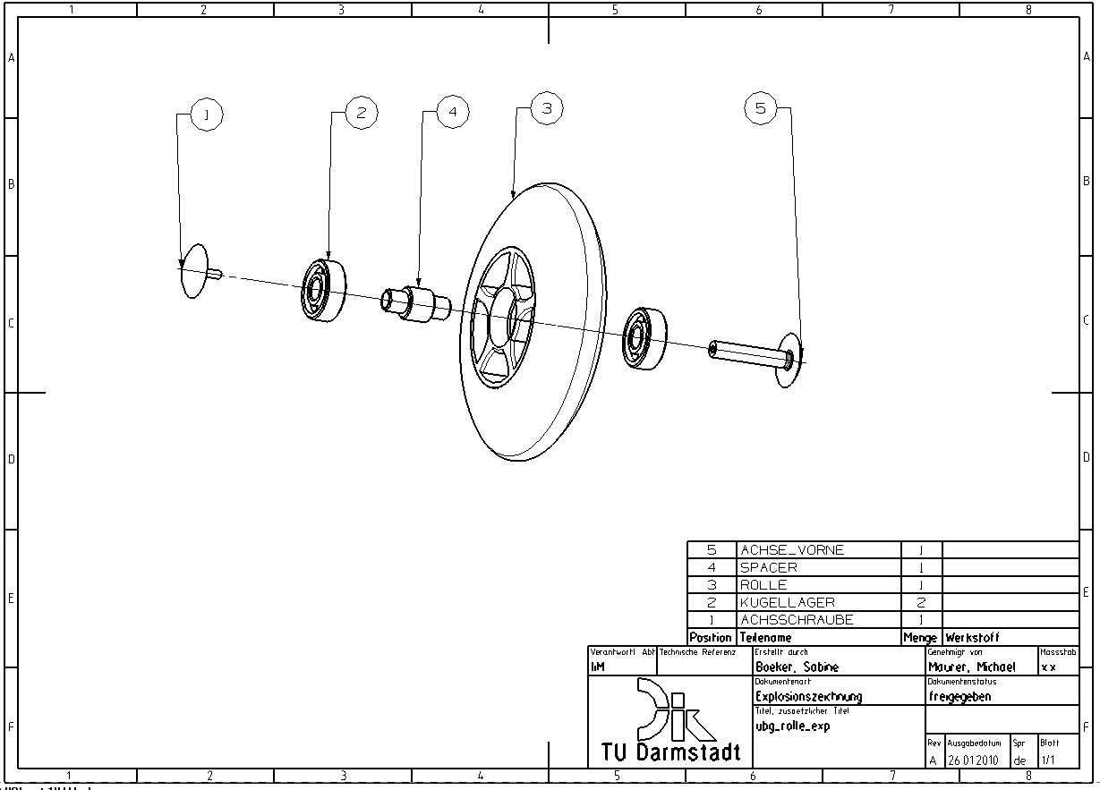
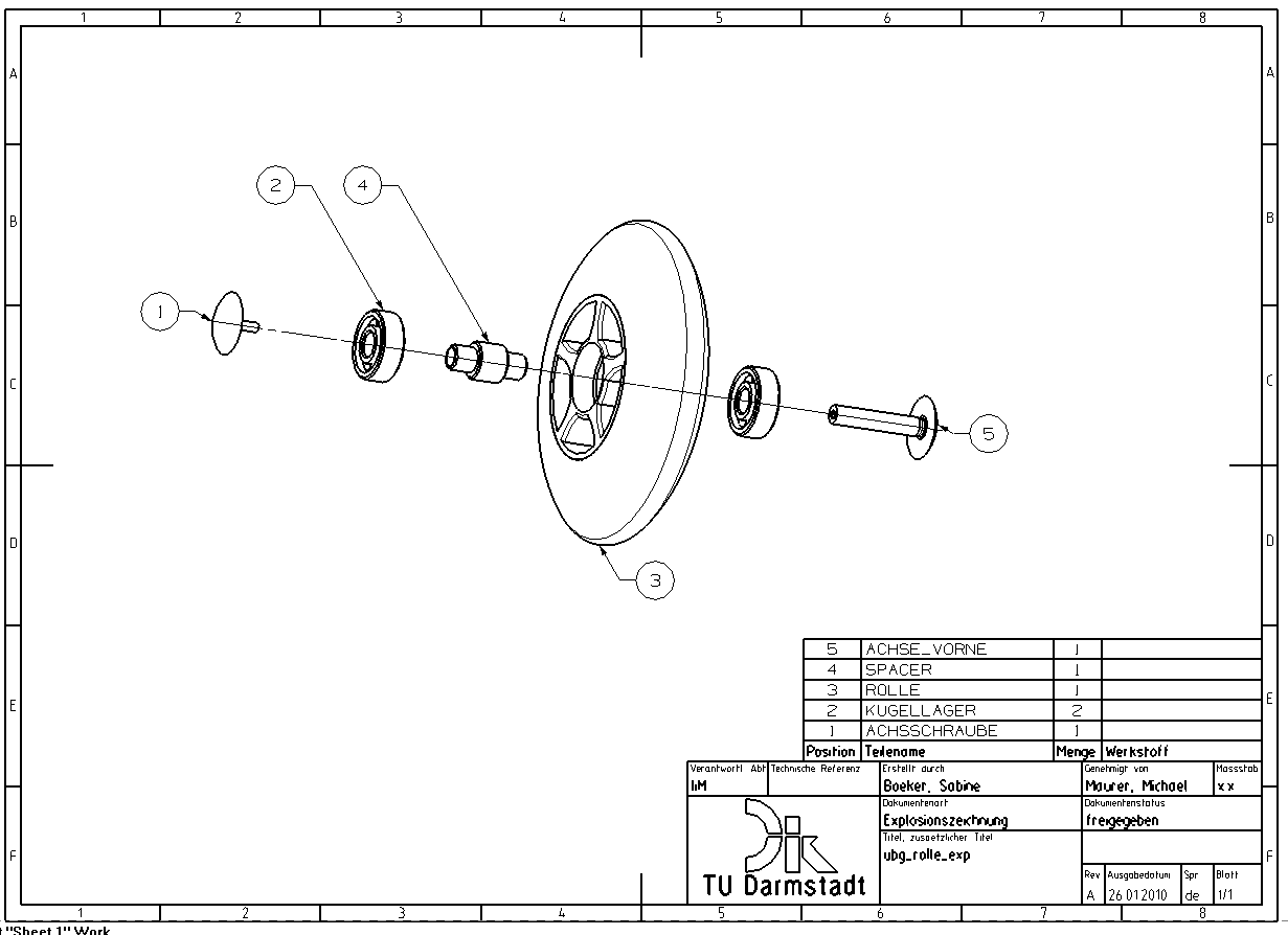
Now your display should look as shown in the figure (see figure "Exploded view drawing with position numbers").
Adjusting the axes
Axes are edited in the 3D Centerline menu. You can call it up by opening the context menu (RMT) and choosing the Edit... option. By moving the arrow, the displayed length of the axis is changed on both sides. For one-sided length manipulation, the Set Extension Individually option must be activated under .
Show/hide datum planes
With "Ctrl+W" Show and Hide you can hide datum planes etc. that are not needed globally.Make sure that the drawing frame is displayed as a curve. Therefore, you should not hide "Curves" with the Show and Hide menu, otherwise the drawing frame will be hidden!
Changing displayed information in the parts list
If, for example, the part names in the parts list still contain the IDs instead of the part names, further settings have to be made.
Use the RMB to click on the bottom of the column and choose Settings from the context menu. Make sure that the entire column is selected, recognizable by the red border.
In the Settings window that opens, select Column on the left. Use the button under Attribute Name to specify "DB_PART_NAME".
Now the names of the parts should be displayed continuously.
However, the text in the title bar has changed. Double-click on the cell and change the text back to "Part name".
The formatting of the title cell has also changed. Click on the title cell with the RMT and select Settings from the context menu.
In the Settings window that opens, select Lettering on the left, set the font to "iso-1" and the text thickness to "Normal Width".
Sort parts list
The order of the components still has to be changed.
- First, select the line you want to edit by clicking on the left edge of the desired line with the RMB.
Attention: always select the whole line directly!
- Choose Cut to cut the row.
- Use the LMB to select the line in which the cut line is to be inserted (again, directly the entire line).
- With RMT-> Paste the line appears at its new position. The remaining rows move automatically and the Position column is updated.
The items of the automatically generated parts list must be sorted from bottom to top according to the following specification:
- all parts made of ferrous materials (which are not standard or purchased parts.
- all parts made of non-ferrous metals (which are not standard or purchased parts)
- all parts made of non-metal materials (which are not standard or purchased parts)
- all standard and purchased parts (parts of the same type and in particular of the same standard, which differ only in their dimensions, are listed consecutively)
Alternative sorting of parts list
The procedure shown in the tutorial is preferable if NX is not used in combination with Teamcenter.
Unfortunately, the "Cut" and "Paste" functions have to be disabled for safety reasons during the course. Therefore, the parts list is sorted as follows:
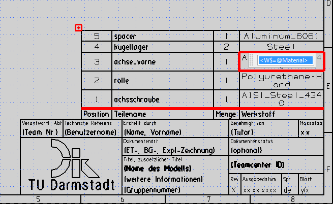
- Double-click with the LMB on the cell with the name of the material.
- An input field appears with the content "<W$=@Material>". (see figure "Cell marked").
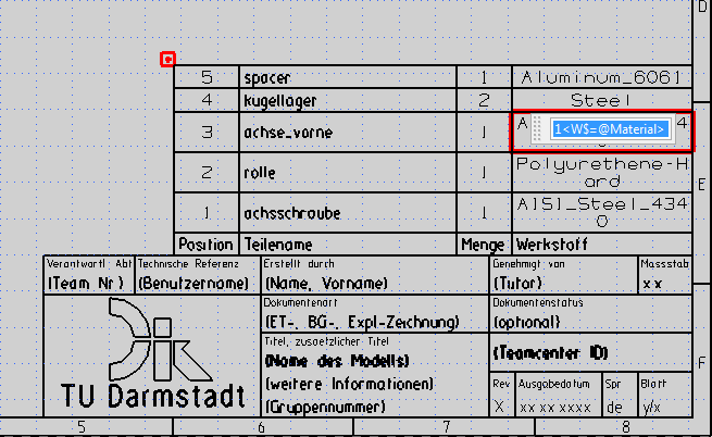
- Leave this entry as it is and insert a number before, in the example a "1". The entry should now look like this:"1<W$=@Material>" (see figure "Cell numbered").
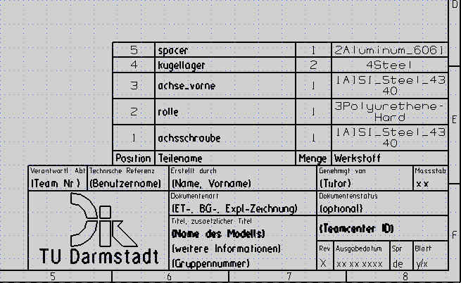
- Repeat this step for each row and select the numbers according to the order in which you want to sort the parts list. (see figure "All Cells numbered").
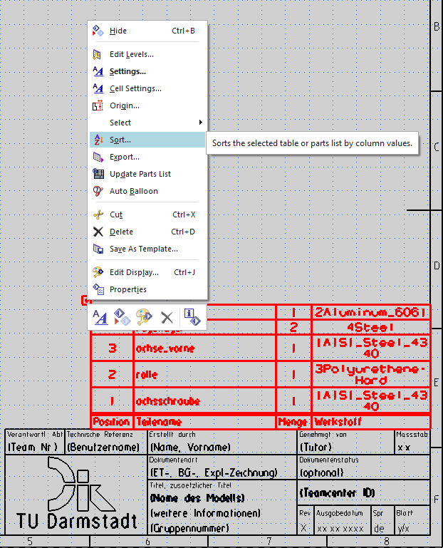
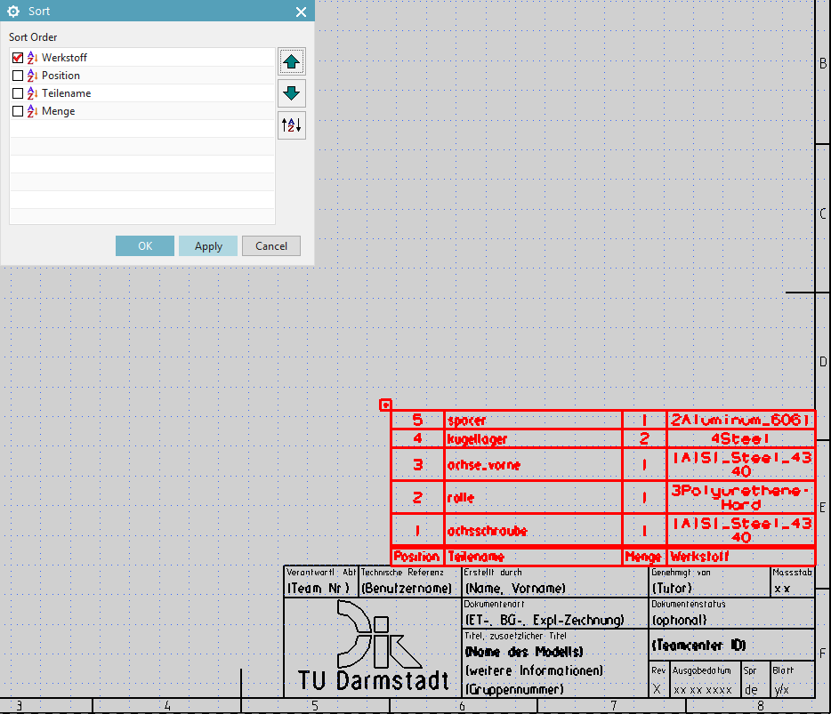
- Now select the entire parts list and use the RMB to open the context menu. Select "Sort". (see figure "Context menu").
- In the menu that now appears, set a check mark at "Material" and click on "Apply". (see figure "Sort oder").
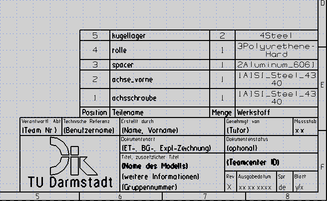
- Now the parts list has been sorted according to your inserted numbers (see figure "Parts list sorted").
- Now select each cell with the material entry again and remove the added numbers. (see figure "Numbers removed").