In this exercise you'll learn about Smart-Modeling. Using it you can add tolerancing to e.g. shafts.
Open the model boss, if you previously created it, and save it as passung according to the naming convention. Otherwise create the model passung and add a cylinder with the following dimensions to it:
| Dimension | Value [mm] |
|---|---|
| Diameter | 20 |
| Height | 50 |
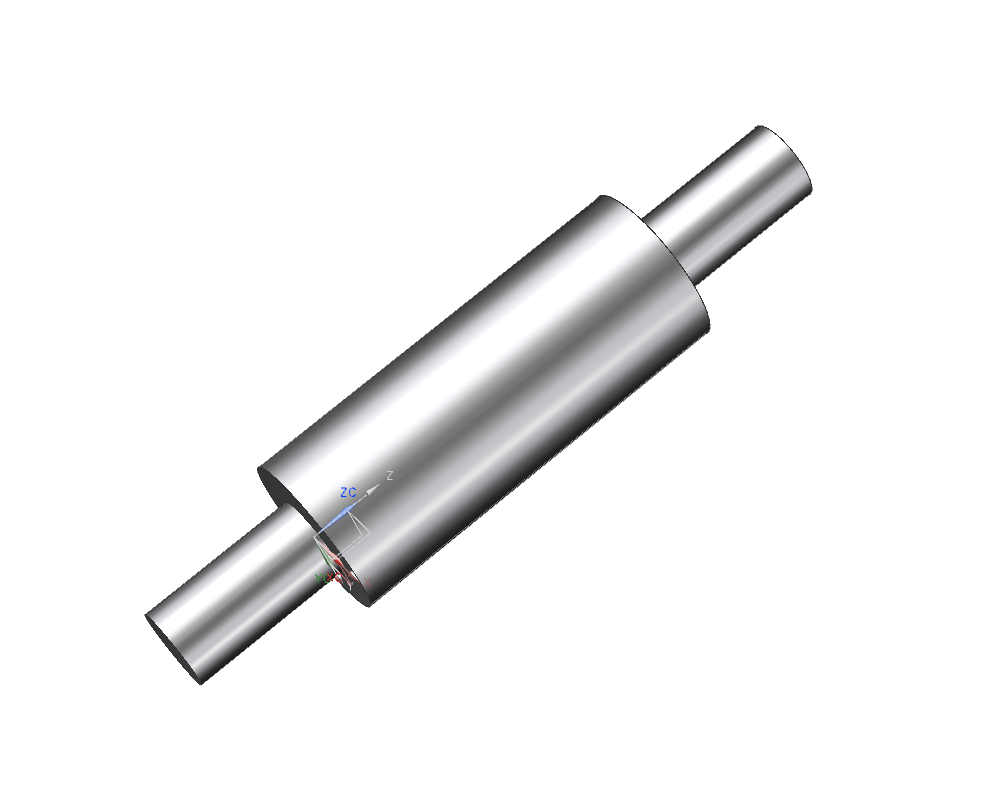
Add two bosses, concentric on the flat surfaces of the cylinder, with the following dimensions:
| Dimension | Value [mm] |
|---|---|
| Diameter | 10 |
| Height | 20 |
(refer figure "Second boss added")
Using the file menu, switch to "PMI" File -> PMI .
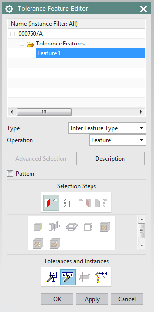
Select Geometric Tolerancing ![]() (in this role, you can find it via Assemblies -> New Explosion or by looking for it with the command finder). The window Tolerance Feature Editor pops up, in which you can see a modeling structure.
(in this role, you can find it via Assemblies -> New Explosion or by looking for it with the command finder). The window Tolerance Feature Editor pops up, in which you can see a modeling structure.
Now select the element, to which you want to add tolerancing.
In this example, choose the small section of the shaft directly within the model by clicking it with the LMB.
To specify the type of tolerance, click ![]() (Create/Edit Tolerance). (refer figure "Tolerance Feature Editor")
(Create/Edit Tolerance). (refer figure "Tolerance Feature Editor")
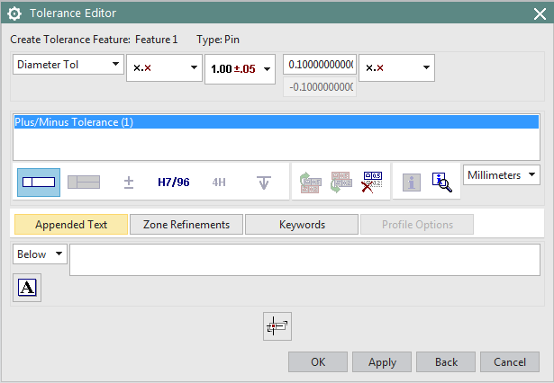
The window Tolerance Editor pops up. Here you can specify a tolerance. To switch from tolerance to fitting, click ![]() . To switch from fitting to tolerance, click
. To switch from fitting to tolerance, click ![]() .
.
Select Fitting.
The whole field of tolerances appears, in which you should specify Deviation (ger. "Lage") g and Grad (ger. "Größe") 6. Confirm and close the window by clicking OK. (refer figure "Tolerance Editor")
The tolerance within the modeling structure is now adjusted to the new information.
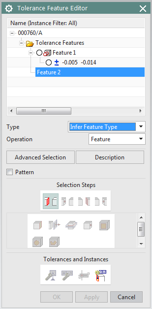
You can always check the Tolerance Feature Editor to see if all your fittings/tolerances have been entered correctly. Click fitting/tolerance within the modeling structure and it'll be highlighted red within the model. (refer figure "Tolerance Feature Editor #2")