
There are two different view options in which you can create Sketches: The Task Environment and the Simple Sketch Mode.
While in Task Environment your view is automatically adjusted to the plane you want to sketch on, the Simple Sketch Mode keeps the current perspective.
The Task Environment-Mode is suitable for creating and editing sketches, since it offers a better overview. Additionally created elements are hidden in this mode, which makes the sketch more visible. Also, NX' icon bars are adjusted for sketch mode.
When changing dimensioning/measurements you can also use simple sketch mode, which you can access by double-clicking the sketch within the Part Navigator.
Create a Model with the name Sketcher according to the naming convention.
Choose Sketch![]() .
.
Define the XY-Plane as your sketch plane by clicking it and confirming by clicking OK. If you accidentally rotate your view away from your sketch plane, you can re-adjust your view by clicking View -> Orient View to Sketch.
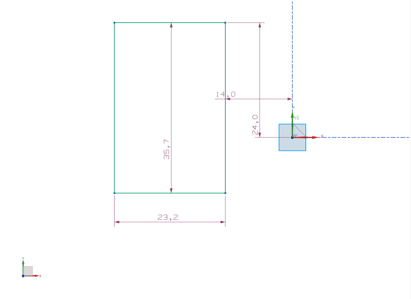
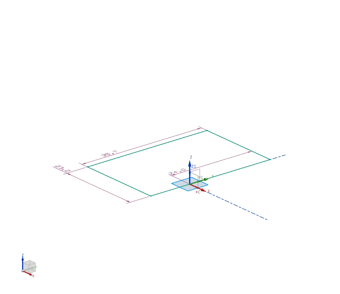
Now choose ![]() and draw a rectangle somewhere on your sketch plane. (figure "Sketch rectangle"). Measurements are automatically created, so called Auto Dimensions (displayed purple or grey). You should now dimension the sketch on your own and replace Auto Dimensions. Measurements you created are displayed blue.
and draw a rectangle somewhere on your sketch plane. (figure "Sketch rectangle"). Measurements are automatically created, so called Auto Dimensions (displayed purple or grey). You should now dimension the sketch on your own and replace Auto Dimensions. Measurements you created are displayed blue.
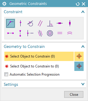
To do so, click "Geometric Constraints"  (refer figure: "Sketch bar") and choose the desired constraint, in this case
 ![]() ("Collinear"). Now click the Y-Axis , a green check appears in the window Geometric Constraints (figure "Geometric Constraints"). To select objects that you want to constrain to your first selection, choose "select object to constrain to" (you can also do this by pressing CMB) and, in this case, select the right side of your rectangle.
("Collinear"). Now click the Y-Axis , a green check appears in the window Geometric Constraints (figure "Geometric Constraints"). To select objects that you want to constrain to your first selection, choose "select object to constrain to" (you can also do this by pressing CMB) and, in this case, select the right side of your rectangle.
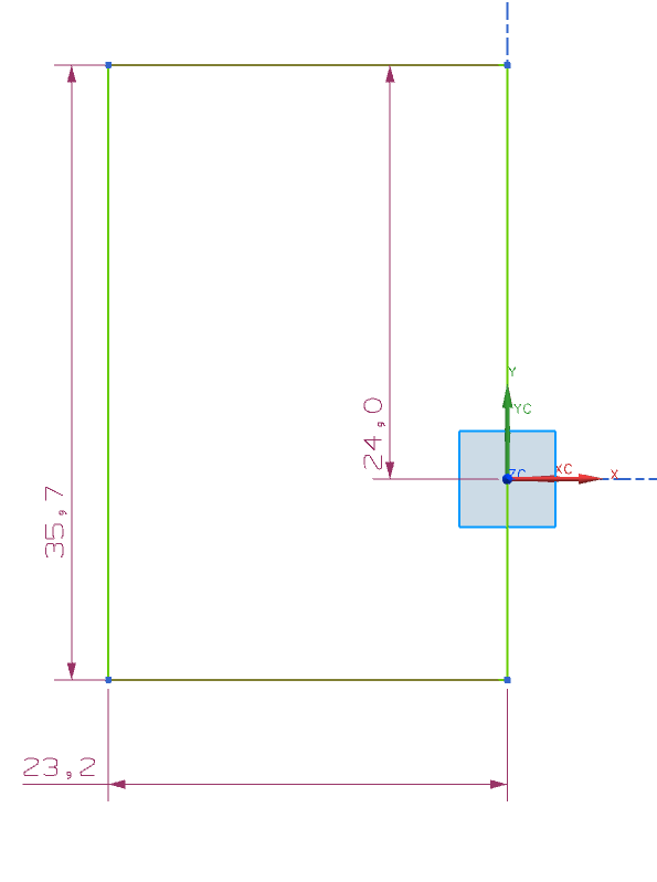
Subsequently, one Auto Dimension less is displayed, since you replaced it with the function ![]() (figure "Sketch").
(figure "Sketch").
Disabling Auto Dimensions
You can disable the function Auto Dimension by clicking Continuous Auto Dimensioning![]() within the sketch bar. Please note, that it is automatically turned on when restarting NX.
within the sketch bar. Please note, that it is automatically turned on when restarting NX.
| Attention: |
|
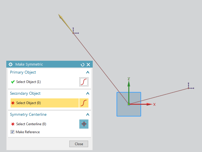
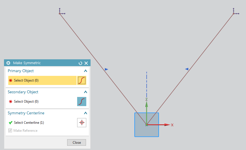
The constraint Make Symmetric ![]() is displayed separately within the sketch bar (refer figure "Sketch bar"). To undertand its function complete the following steps: Add two random, not identical, lines to your sketch, that start in the point of origin. Click Make Symmetric
is displayed separately within the sketch bar (refer figure "Sketch bar"). To undertand its function complete the following steps: Add two random, not identical, lines to your sketch, that start in the point of origin. Click Make Symmetric ![]() and select one line (refer figure: "Make Symmetric before"), then the other line, and then a symmetry center line, in this case the Y-Axis. The new line is symmetrically adjusted to the other, or mirrored across the center line. (refer figure: "Make Symmetric after").
and select one line (refer figure: "Make Symmetric before"), then the other line, and then a symmetry center line, in this case the Y-Axis. The new line is symmetrically adjusted to the other, or mirrored across the center line. (refer figure: "Make Symmetric after").
Now click Finish Sketch![]() to exit sketch mode.
to exit sketch mode.
Now you can see your sketch within the Part Navigator ![]() . Double-click on Sketch (1) "Sketch_000" to open the sketch you just created. (figure "Sketch view"). Now you can select any measurement and edit it. When you want to switch to a sketch view in Task Environment, you have to click
. Double-click on Sketch (1) "Sketch_000" to open the sketch you just created. (figure "Sketch view"). Now you can select any measurement and edit it. When you want to switch to a sketch view in Task Environment, you have to click ![]() . (Note the small arrow on the lower left of the icon!)
. (Note the small arrow on the lower left of the icon!)
If you want to start sketch mode directly in Task Environment, choose Sketch in Task Environment ![]() .
.
On the following pages sketches are alwayes viewed in Task Environment!