Create a new model with the name sketch according to the naming convention.
Sketch
Click Sketch in Task Environment ![]() . You can find this icon within the tab Modeling.
. You can find this icon within the tab Modeling.
Now you have to define a drawing plane. Select the YZ-Plane and confirm with OK.
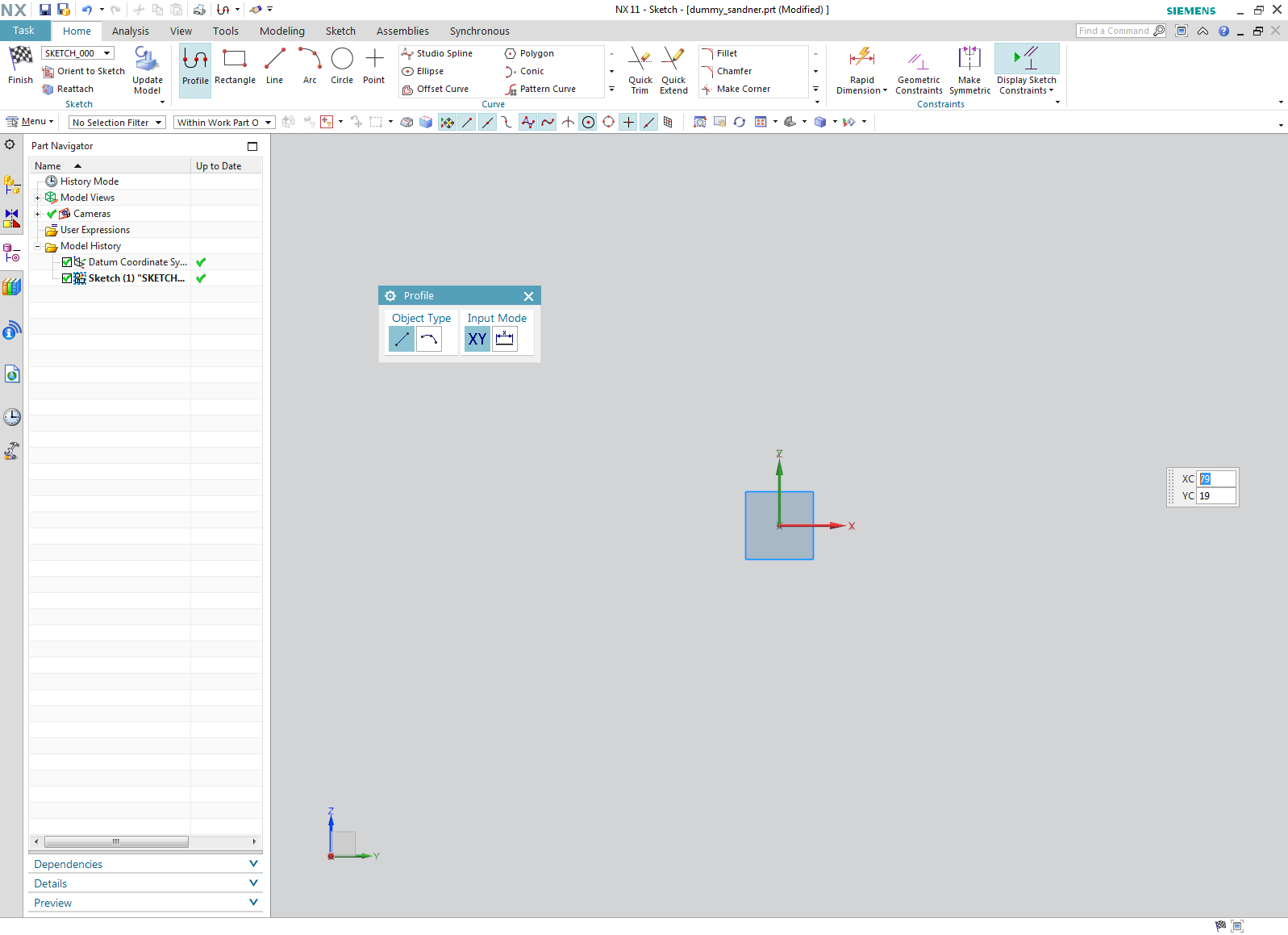
You should draw an L-Profile. You automatically entered the mode for drawing lines when entering sketch mode. Your NX screen should look like the one on the right. If not, click ![]() (figure "Drawing lines").
(figure "Drawing lines").
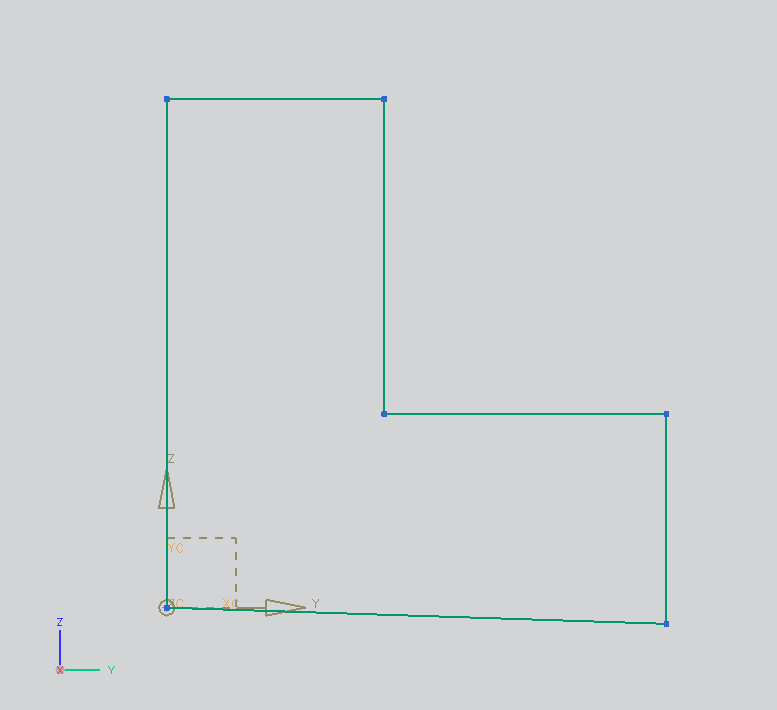
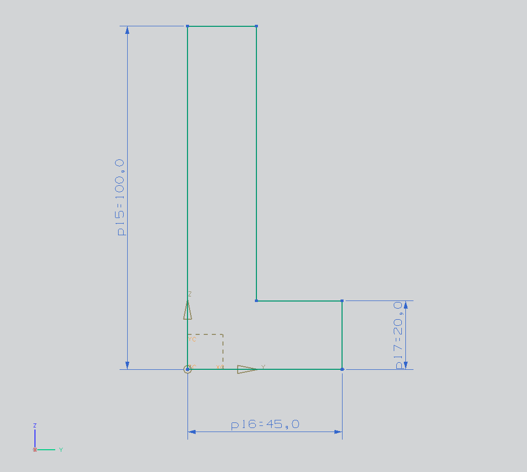
Draw a L, like displayed in the picture on the right. (figure "L created")
Sketch mode allows you to place points (e.g. endpoints of lines, midpoints of circles) directly by entering values.
| Attention: |
Sketches always have to be fully constrained. Auto-constraints are only basic help by NX - your modeling strategy is not reflected by this. This is why you have to replace auto constraints with your own constraints / dimensioning. |
| Hint: | If you made a mistake when drawing, deactivate the profile-tool by clicking |
Constraints
Click Collinear ![]() . Select the lower horizontal line of the L, and as the second element the horizontal axis of the coordinate system.
. Select the lower horizontal line of the L, and as the second element the horizontal axis of the coordinate system.
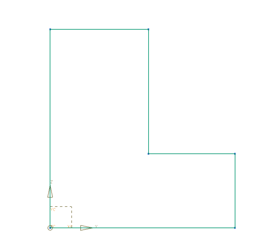
The lower horizontal line of the L will now be aligned with the horizontal axis of the coordinate system. Do the same steps again to align the vertical line of the L. (figure "L aligned")
| Hint: | The Dialog on the lower egde of your screen says: "Sketch is fully constrained with auto dimensions". After you constrained and dimensioned your sketch on your own, it'll change to: "Sketch is fully constrained". |
Highlight both short sides of the L. By clicking Equal Length ![]() they are adjusted to the same length.
they are adjusted to the same length.
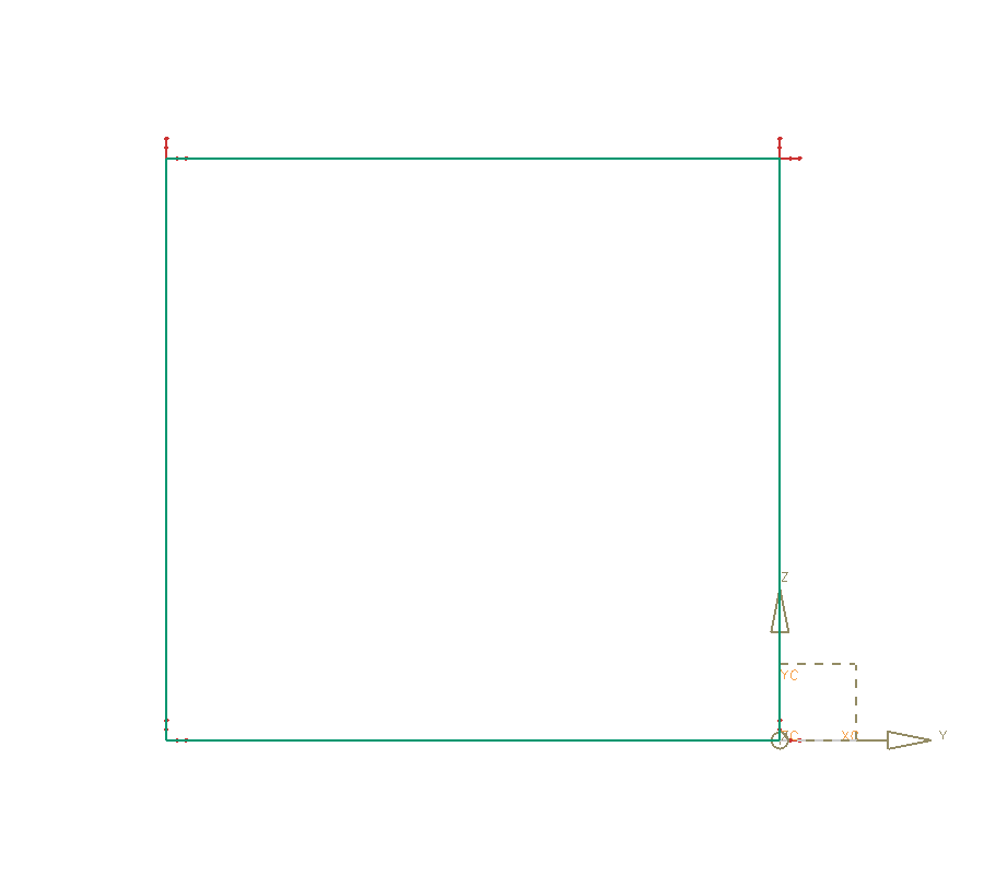
When constraints are missing in your Sketch, NX marks the missing degrees of freedom with red arrows next to the respective points. Two degrees of freedom are still present in the picture on the right. The vertical line on the left can still be moved horizontally, so you can see horizontal arrows on its endpoints. The upper horizontal line can still be moved vertically, so the arrows are displayed vertically. (figure "degrees of freedom")
The following constraints can be used:
| Icon | Name | Function | ||
| Coincident | Connects two points to each other. | |||
| Equal Radius | Equal radius for arcs or circles. | |||
| Cocentric | Cocentric circles / arcs (same midpoint). | |||
| Tangent | Adjusts lines/curves to be tangent to an arc/circle. | |||
| Parallel | Parallel constraint for axes, lines, etc. | |||
| Perpendicular | Adjusts two elements perpendicular. | |||
| Constant Angle | Sets an angle between two lines to be constant. | |||
| Equal Length | Equal length for lines | |||
| Collinear | Parallel with distance = 0 | |||
| Horizontal | Horizontal alignment | |||
| Vertical | Vertical alignment | |||
| Constant Length | Defines a distant to be constant. | |||
| Point on Curve | A endpoint can be placed on a line or arc. | |||
| Fixed |
Fixes an element to its position.
|
Dimensioning
Click Rapid Dimensions  , to create measurements.
Select the long vertical line of the L. As length, enter 100 mm.
Dimension your sketch as shown in the picture on the right. (figure "L dimensioned").
| Hint: |
|
Make sure your sketch is fully constrained.
End sketch mode with ![]() .
.
Save your model.
| Hint: | If you want to edit a sketch later on, RMB-click on it within the part navigator and choose Edit... |
References
Especially with complex sketches, it can be convenient to work with references. These are datums that can be created from sketch elements. How to use them is illustrated in the following example:
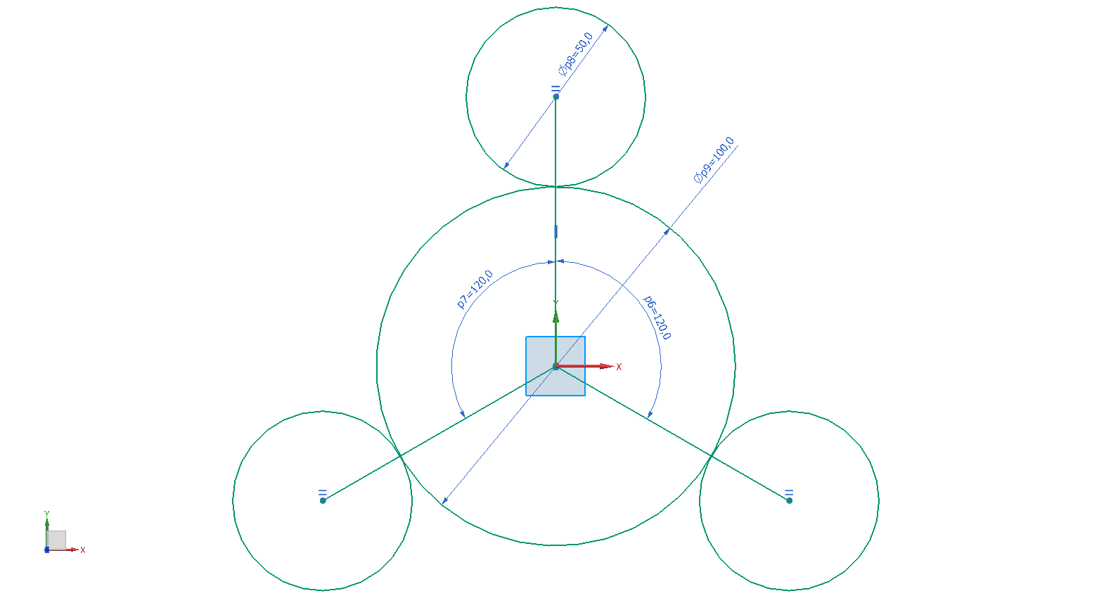
The mount on the right should be created by extruding a sketch. The diameter of three cylinders is known. They are placed symmetrically around a imaginary circle in the middle, of which the diameter is known as well. To create the mount, 3 lines with an angle of 120° to eachother are created. The endpoints of those represent the midpoints for 3 circles whith the diameter D=50mm. To fulfill the requirement, that the 3 small circles surround a bigger circle (diameter D=100mm), this circle is created in the point of origin. By using the Tangent ![]() constraint, the small circles are aligned around the big one. (refer figure "Sketch created"). Now you can create similar geometries, by only changing the diameters specified before.
constraint, the small circles are aligned around the big one. (refer figure "Sketch created"). Now you can create similar geometries, by only changing the diameters specified before.
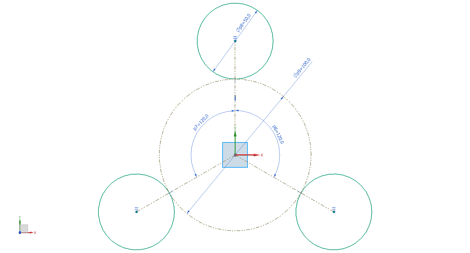
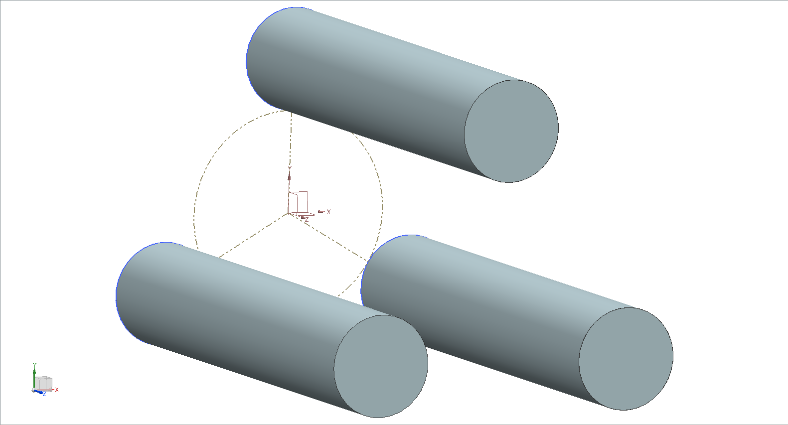
To extrude the sketch properly, the big circle and the 3 lines have to be references. To convert those elements, click them with RMB and choose Convert To/From Reference ![]() (refer figure "Sketch with references"). References can be handled like normal sketch elements (constraints, dimensioning, etc.), at the same they'll be ignored outside of sketch mode. (refer figure "extruded properly").
(refer figure "Sketch with references"). References can be handled like normal sketch elements (constraints, dimensioning, etc.), at the same they'll be ignored outside of sketch mode. (refer figure "extruded properly").
You can convert references back to normal sketch elements by following the same steps.
This is a summary of the most importint tools within sketch mode:
| Tool | Function | Icon |
|---|---|---|
| Profile | draw profiles (can contain arcs) | |
| Line | draw lines | |
| Arc | draw arcs | |
| Circle | draw circles | |
| Quick Trim | trim sections of lines | |
| Fillet | round off edges | |
| Rectangle | draw rectangles | |
| Make Corner | connect the ends of two lines to a corner |
| Hint: | Note, that there is never just one correct option to create 2D-sketches, there are many strategies to fulfill your goals. This is why you should learn to create sketches using different steps/strategies. |