Enter sketch mode and choose the XY-Plane as your drawing plane. Create the D, I and K in the same sketch. (For demonstrational purposes, the six-line rule for sketches is ignored here)
Make sure, that this function ![]() (Create Inferred Constraints) is active in sketch mode. Otherwise, your sketch may not be fully constrained later on.
(Create Inferred Constraints) is active in sketch mode. Otherwise, your sketch may not be fully constrained later on.
If you can not find this function, enter "Create Inferred Constraints" into Command Finder and let NX show you where this function is located by hovering over it with your mouse in Command Finder.
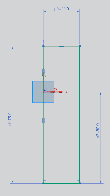
Firstly, create the I with a rectangle ![]() . Adjust the left side to the vertical axis with
. Adjust the left side to the vertical axis with ![]() . You can find the measurements for the rectangle in the picutre on the right. (figure "I measurements").
. You can find the measurements for the rectangle in the picutre on the right. (figure "I measurements").
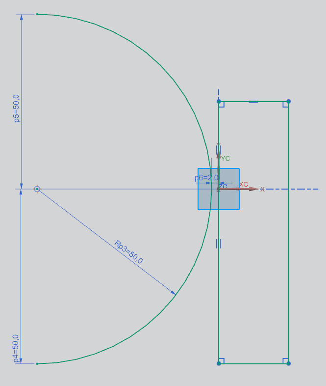
Next, you should create the D. Use ![]() , to create an arc like shown in the figure on the right. (figure "D measurements")
, to create an arc like shown in the figure on the right. (figure "D measurements")
| Important: |
|
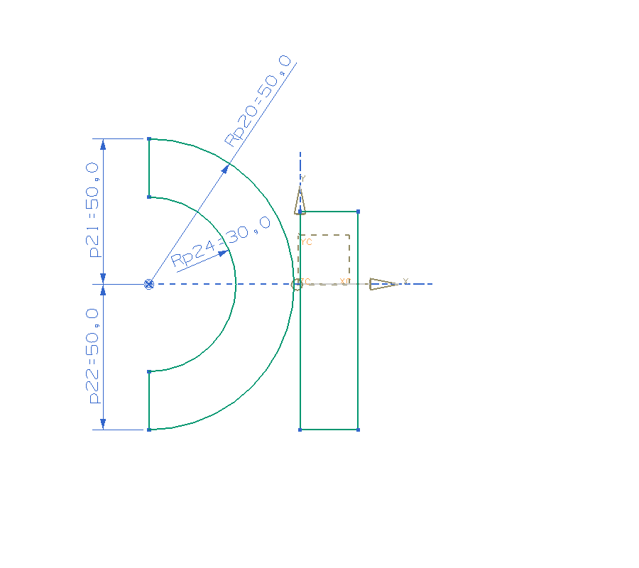
Create a second arc.
Apply constraints in a way that the second arc is concentric ![]() to the first one.
to the first one.
Connect the endpoints of the arcs with lines ![]() , so that they form a D. The lines should be aligned vertically
, so that they form a D. The lines should be aligned vertically ![]() .
.
Eventually you have to make both vertical lines colinear ![]() . (figure "D finished")
. (figure "D finished")
Make sure that the message Sketch is fully constrained is displayed. It's displayed in the bar on the lower edge of your screen.
If there are problems with applying constraints, there are two options to help you:
- Display every previously applied constraint by clicking Display Sketch Constraints
 , or
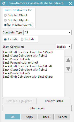
, or - Go to Show/Remove Constraints
 .
.
All in Active Sketch shows you every constraint that is applied. You can select every single constraint, change their order with the small arrows or remove constraints with Remove Highlighted. (figure "Show/Remove Constraints")
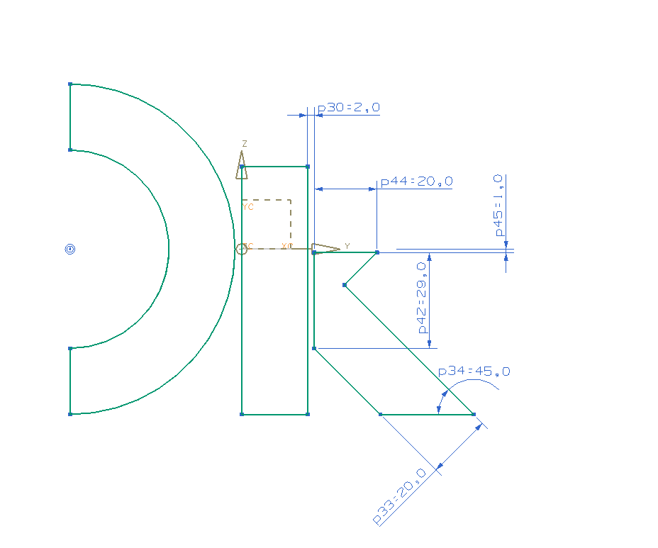
Now, create the contour of the K. Make sure, that the horizontal line of the K is not colinear with the coordinate axis, but at a distance of 1mm to it. The other letters should also end on the same Y-Coordinate. The function Perpendicular ![]() and Parallel
and Parallel ![]() are useful to create perpendicular or parallel lines. (figure "K dimensioned")
are useful to create perpendicular or parallel lines. (figure "K dimensioned")
Draw a horizontal line that crosses the D as well as the I. It should be placed 1mm above the horizontal axis.
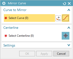
Mirror this line across the horizontal axis Insert -> Sketch Curve -> Mirror Curve... ![]() . Firstly, select the newly created line (for "Select Curve") and subsequently select the horizontal axis as Centerline ("Select Centerline"). (figure "Mirror Curve")
. Firstly, select the newly created line (for "Select Curve") and subsequently select the horizontal axis as Centerline ("Select Centerline"). (figure "Mirror Curve")
Confirm by clicking OK.
Now you should have two parallel lines. Trim any unnecessary sections with the function Quick Trim ![]() .
.
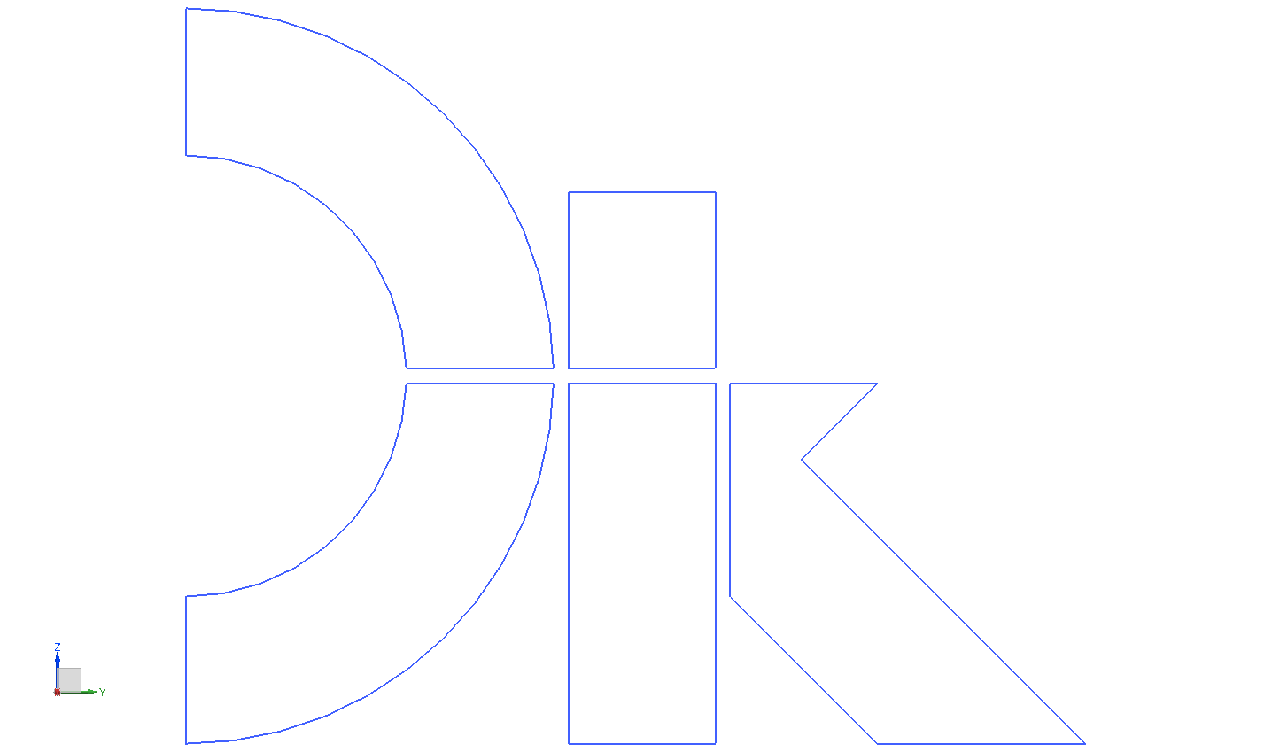
Delete all unnecessary sections so that your sketch resembles the sketch shown in figure "DIK trim".
Trimming unwanted sections of lines, could cause you to lose constraints sometimes. These may have to be added back in to make your sketch fully constrained.
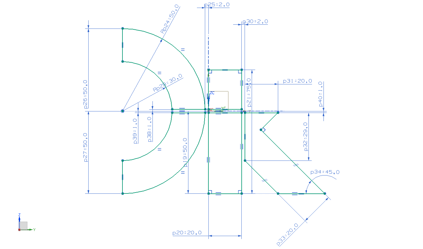
The small yellow arrows show which references still have to be defined. Add measurements as shown in the picture on the right to fully constrain your sketch. (figure "DIK finished")
Save your Model.
NX's sketch mode has defined color coding. Dimensions are displayed in different colors, depending on their necessity. If they are unnecessary, the dialog bar indicates Sketch contains over constrained geometry.
The most important colors of sketch mode are:
| Color | Meaning |
|---|---|
| Green |
|
| Blue |
|
| Red |
|
| Pink |
|
| Grey |
|
| Green |
|
The following list contains all important icons for working in sketch mode:
| Tool | Function | Icon |
|---|---|---|
| Profile | draw curves/profiles (can contain arcs) |  |
| Line | draw single lines | |
| Arc | draw arcs | |
| Circle | draw circles | |
| Quick Trim | trims sections of lines | |
| Fillet | round off edges |  |
| Rectangle | draw rectangle |  |
| Make Corner | connects the ends of two lines to a corner | |
| Mirror Curve | mirrors elements across a center line | |
| Offset Curve | creates a scaled version of selected elements |
| Tool (for references) | Function | Icon |
|---|---|---|
| Inferred Dimension | add measurements/dimensions to your sketch | |
| Constraints | add constraints | |
| Display Sketch Constraints | Show all constraints in the sketch | |
| Show/Remove Constraints | Dialog used for displaying and removing constraints | |
| Inferred Constraints and Dimensions | configure constraints |
| Other important functions | Function | Icon |
|---|---|---|
| Finish Sketch | Close sketch mode |  |
| Orient View to Sketch | Adjust your view to the drawing plane |