In this exercise, you will learn about Assembly Clearance analysis.
This function checks the assembly for possible overlaps and indicates where and between which components the error can be found. This enables the modules to be checked for a perfect assembly.
Under Analysis -> Assembly Clearance -> Perform Analysis you will find the window Clearance Analysis. Here you can set the extent to which you want to perform the penetration analysis.
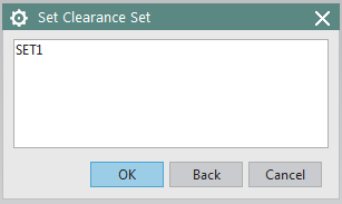
If the Set Clearance Set window (Figure "Set Clearance Set") opens, select "Set 1" and confirm with OK. This takes you directly to the Clearance Browser window.
- If you exactly want to know where an overlap is, select a line with RMB and choose Study Interference from the context menu. The overlap is highlighted in red. Alternatively, you can also display this view by double-clicking the LMB.
- The columns Selected Component and Interfering Component specify the components that are interpenetrated with each other.
- In the Type column, you can see the type of penetration. A distinction is made between Existing and New:
| Existing | This identifies all penetrations of a previous analysis. |
| New | This identifies all new penetrations. (If you have installed a new part in an assembly after an analysis, it will be marked with New in the next analysis. |
and between Touching and Hard:
| Touching | This is used to identify parts that come into contact but are not critical to each other. |
| Hard | This identifies the parts that penetrate (cut) each other. |
| Caution: | For threads, overlaps are allowed and unavoidable, otherwise they are not allowed! |