For the analysis of assembled assemblies it can be advantageous to make cuts through the entire assembly. This makes it easier to identify correlations and possible overlaps.

Creating a dynamic section view in the 3D model
Open the subassembly ubg_getriebe of the assembly bg_Mindstorms (see Figure "ubg_getriebe").
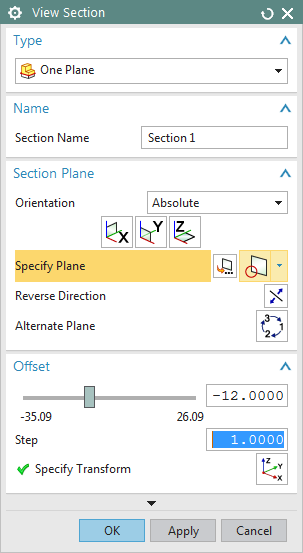
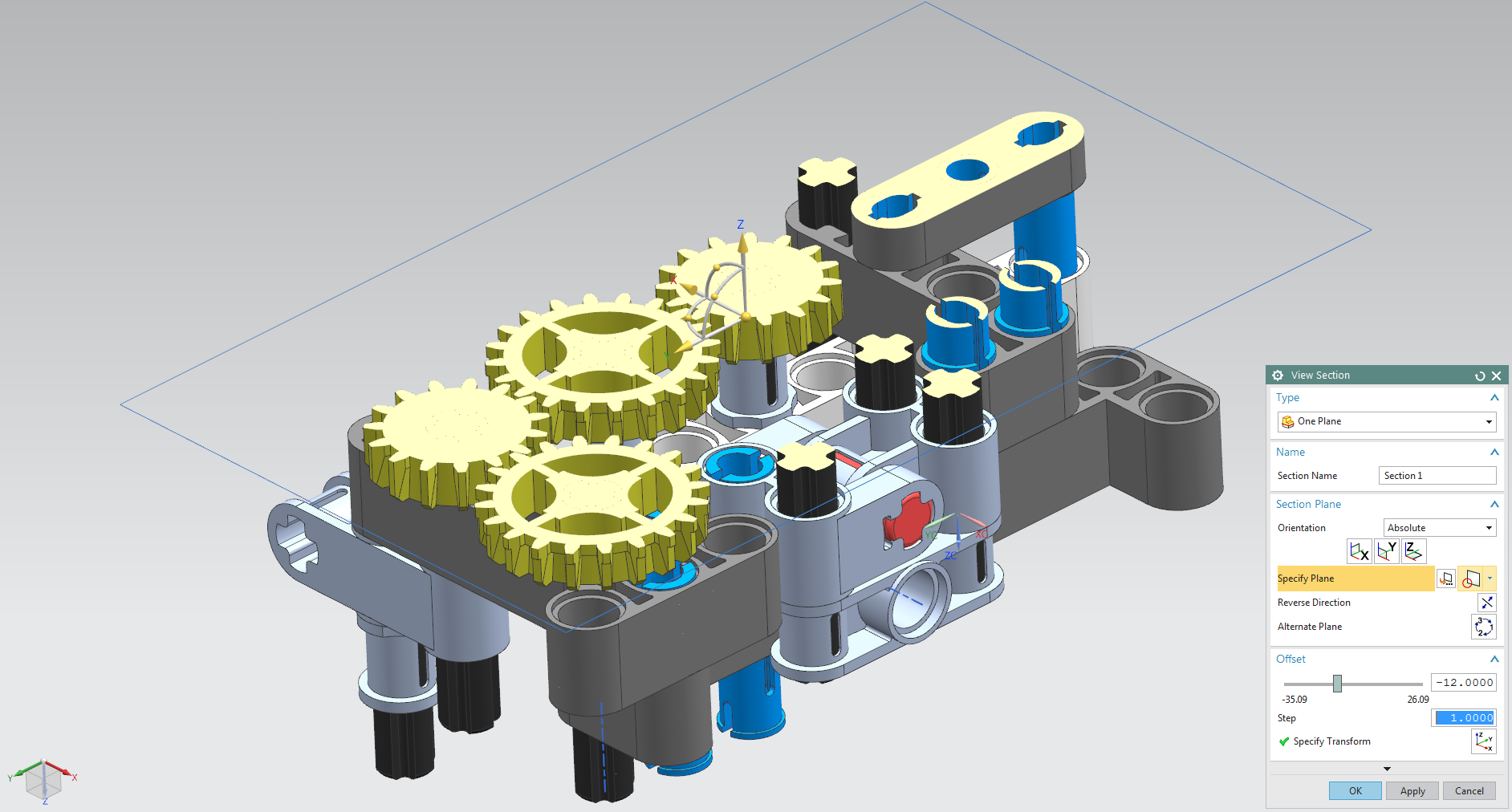
Now select View -> Section -> New Section . In the dialog that opens, you can define all settings for creating the section (see figure "View Section").
In our case, select the option  under Type . Under Section Plane select the section plane, in this case the XY plane. Now you can parallely move the plane with the slider under Offset and get a three-dimensional section through the assembly. In addition, a Dynamic WCS is available in the work window, which allows you to rotate and move the section. This gives you the opportunity to create a vivid cut.
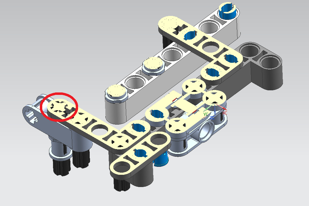
In the present example, it is possible to check, for example, whether the engagement of the gears among each other is correct (see figure "ubg_getriebe_geschnitten XY"). To do so, zoom in on the gear wheels of the gear unit. You can now see that the teeth that engage with each other are at a sufficient distance from each other and that there are no overlaps.
You will see an overlap if you move the cut to a distance of -2.00. On closer inspection, it can be seen that the 4-er_stange is rotated relative to the 4er_winkelbalken (see figure "ubg_getriebe overlap").
Alternatively, the options ![]() or
or  for defining the section view can be selected, which are often also very helpful. The associated setting options are self-explanatory and can be tried out by you using the example part.
You can cancel the cut by selection View -> Section -> Clip Section.
This tool is very helpful for your own analysis of your assembly. Overlaps can be searched by the Penetration Analysis (see chapter 6.5 "Interference Analysis") and represented by red markings. A section at this point often gives you a closer insight into the possible errors.
Handling of several section views
When assembling or analyzing larger models, it is helpful to create multiple section views and switch between them. The Assembly Navigator provides you with an overview of this. Expand the Sections menu item. You can see that so far only one section has been created, which is called "Section 1" and is currently active.
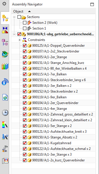
Now create another section by using the RMB in the Assembly Navigator to click on Section and select New Section from the drop-down menu. The new cut is to be named "Schnitt neu 2". Create it parallel to the XZ plane with an offset of -16.00 and confirm with OK. In the Assembly Navigator you will now see the following view (see figure "Assembly Navigator Section 2"). This means that in modeling mode two section views have been created. Currently you are working in the view "Section 2 (Work)". A right-click on the entries in the Assembly Navigator offers you the following options:
- Make Work Section: Activates the section view (only available if the selected section is not already active) (also possible by double-clicking)
- Clip/Unclip: Switches the respective section on/off (only available if the selected section is active)
- Show Section Curves in Work View: Shows the boundary lines of the cut parts; useful to distinguish between the different parts.
Advanced Methods
The Section View function offers many more options for analyzing section views. Below are some very useful functions as examples.
Select the section "Section 2" just created as active. Use the RMB to click on the entry in the Assembly Navigator and choose Edit
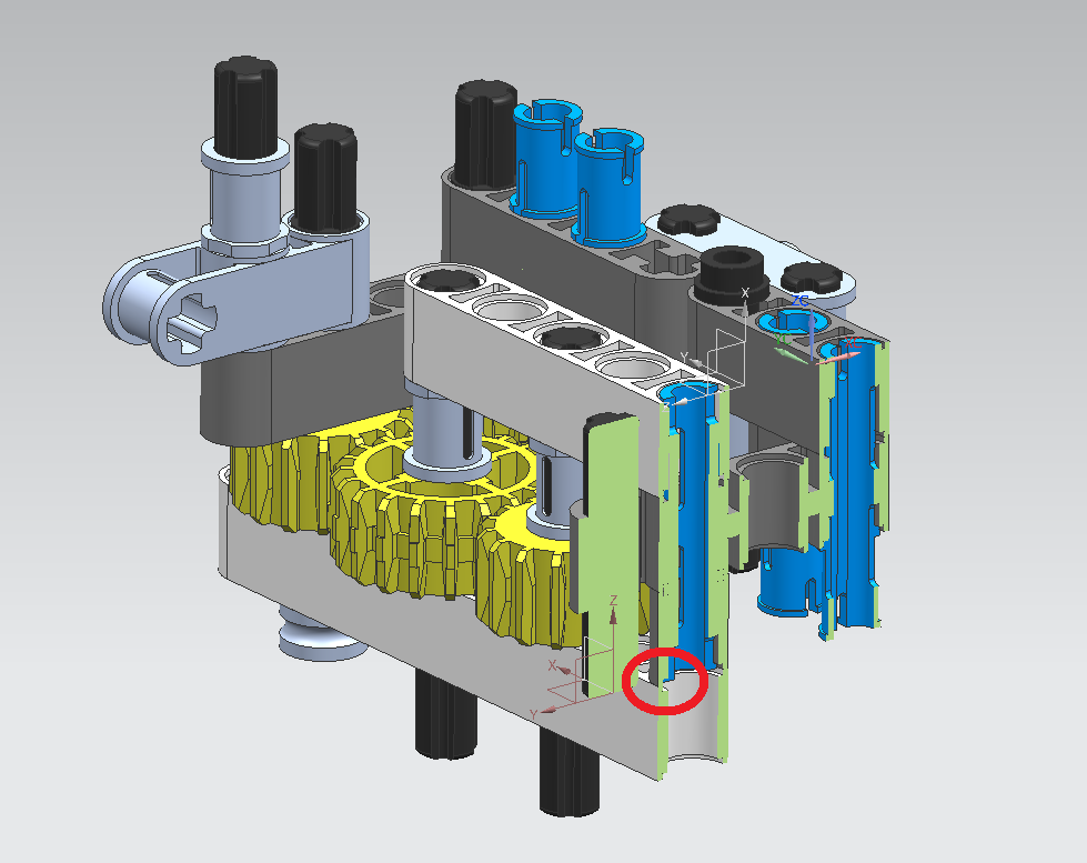
.Now it is to be examined whether the Steckverbinder_lang is inserted far enough into the 90_4er_Winkelbalken. The critical location (see figure "ubg_getriebe critical location) is shown in the sectional view, but unclearly displayed.
One way to make the cut clearer is to change the color of the cut according to the body colors. To do this, go to the View Section window, select the tab Cap Settingsand select  from the dropdown menu under Color Option. This gives you a better overview of the interfaces of several bodies, provided they have different colors. As now clearly visible, the bodies viewed here do not overlap.
In addition, you can activate the display of the boundary curves of the components in the respective section view under the tab Section Curve Settings. This makes it easier to recognize the distinction between the components.
Alternatively, you can use Show Section Curves in Work View to highlight the edges, which also greatly improves clarity.