We now begin by adding different dimensions to the part "stangen_querverbinder". You will find them in the top left corner of the PMI menu bar under Dimensions.
Overview:
The dimensioning methods described in chapter 7 are already known to you and are therefore only briefly explained here.
| Dimensions | |
|
Creates a linear dimension between two points. Select two corner points or an edge and drag your dimension to the desired position. |
|
 |
Creates a radius or diameter dimension. For holes, select the inner surface to obtain information about the thread standard and the hole depth. |
 |
Creates an angle dimension. Select 2 reference planes or edges between which the angle dimension is to be made. |
 |
Creates a chamfer dimension. First select the chamfer and then a reference plane / edge. You receive a dimension of the chamfer depth and angle in relation to the reference plane / edge. |
 |
Creates a thickness dimension to measure the distance between two curves. Select the two relevant curves. |
 |
Creates an arc length dimension. Select the edge of the arc to be dimensioned. |
 |
Creates a coordinate dimension. |
 |
Creates a dimension that automatically adapts its dimension type to the selected object. |
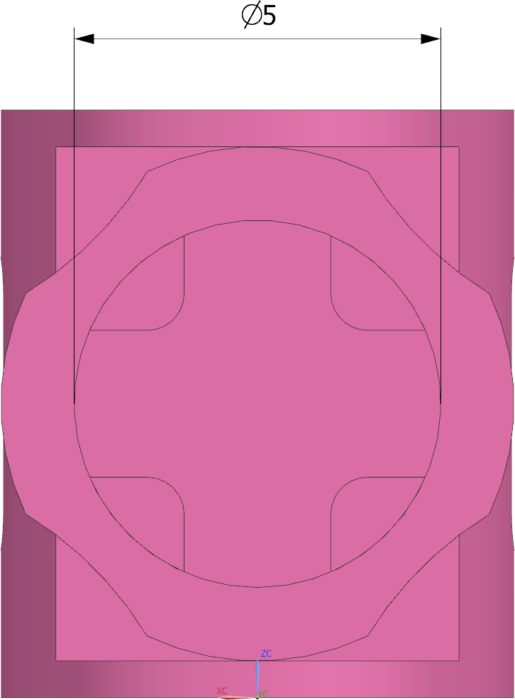
Select the "Back" view under Model Views in the Part Navigator. Now dimension the inner diameter of the cylinder. Click on Radial ![]() and select the inner edge of the cylinder.
and select the inner edge of the cylinder.
Under Measurement->Method you can select whether you want to display the value radially or diametrically. Alternatively, you can also execute the dimensioning with the Rapid ![]() function. (See figure "Inner diameter dimensioning")
function. (See figure "Inner diameter dimensioning")
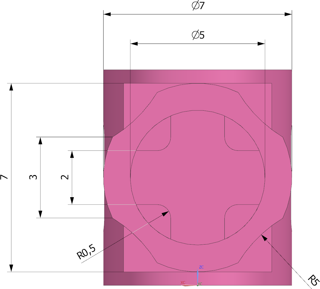
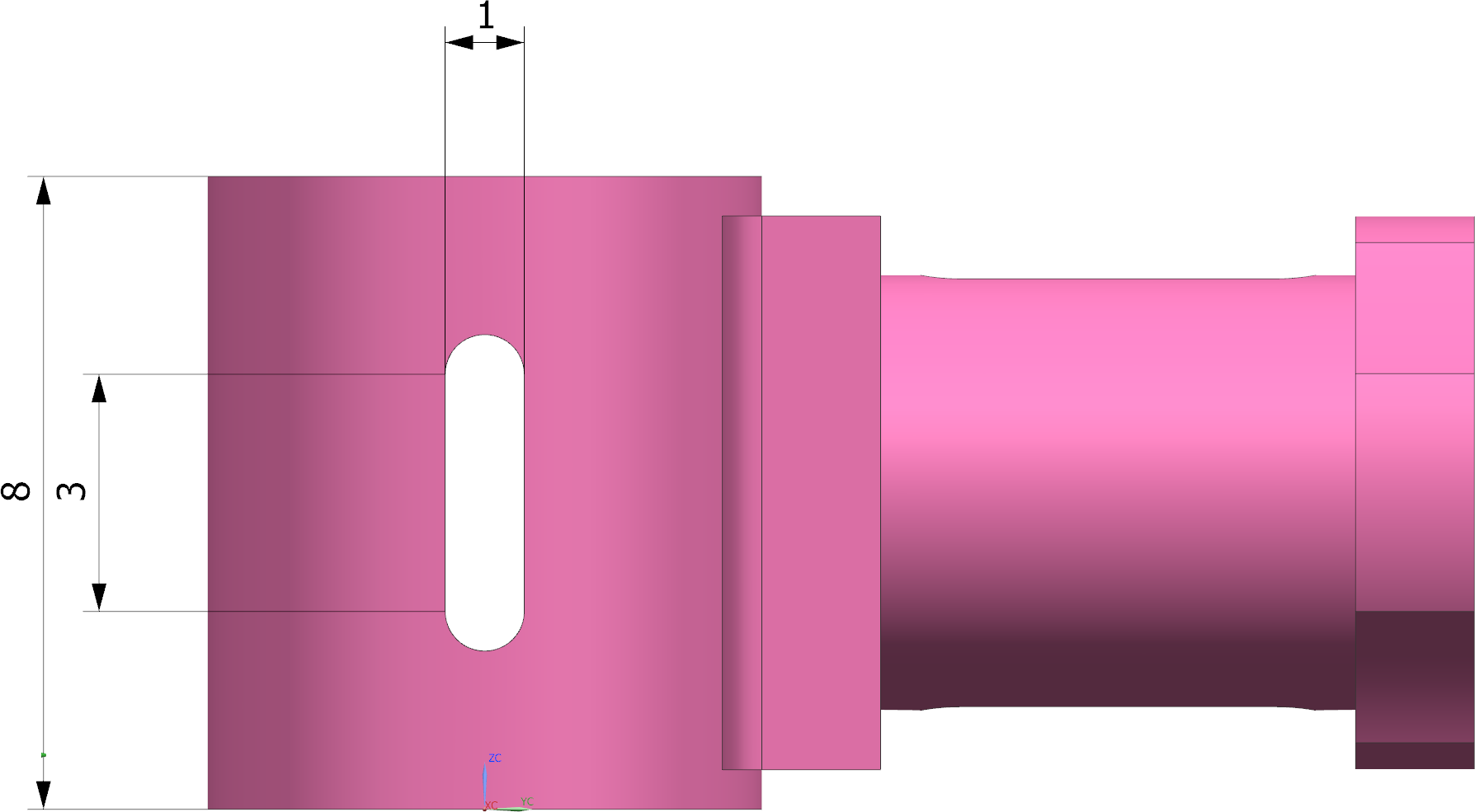
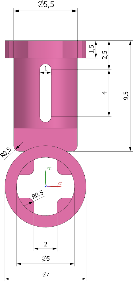
Now add the remaining dimensions for the "Back" view and then add all other dimensions as shown in the illustrations.
The dimensions of the inner form elements are added in the next chapter 9.1.3 "Insert Section View".
| Note: |
|