Open the model cylinder, if you previously created it, and save it as male_thread according to the naming convention. Otherwise create the model male_thread and add a cylinder with the following dimensions to it:
| Dimension | Value [mm] |
|---|---|
| Diameter | 20 |
| Height | 50 |
Symbolic thread

The window Thread pops up.
Select Symbolic and highlight the cylinder's mantle.
The necessary values for the thread are calculated automatically, you just have to specify its lenght and enter a starting point. In this case enter 20mm.
Now click Select Start and select the flat surface on the right.
If the thread's axis points into the wrong direction, you can switch directions by clicking Reverse Thread Axis
Confirm by clicking OK.
Confirm again by clicking OK.
The thread should now be represented by a blue dashed line on the cylinders mantle.
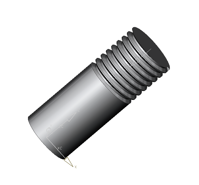
Now delete the Symbolic Thread and create a Detailed Thread using the same method. Observe the difference. For modeling there is no difference, but the CPU load is increased for detailed threads. (refer figure "symbolic thread") and (refer figure "detailled thread")