You also need the specification you have just created and the corresponding master model achse_hinten_tpd.
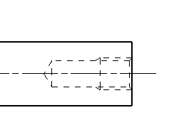
The drawing contains a blind hole, which is hidden in the side view. In technical drawings, hidden edges must be made visible to be used as a reference for dimensioning. (see figure "Hidden displayed blind-hole")
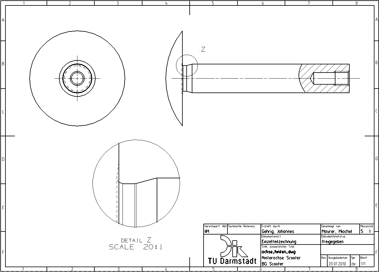
Since rotating parts must not be cut along their axis, a breakout is used to obtain a full view of the blind hole thread.
Creating the spline
Before you start creating the breakout, you need to limit the area of the breakout with a spline. To do this, the Active Sketch View must be activated so that the spline is directly connected to the view. This allows it to be selected later and is also shifted when the view of the breakout is moved.
To activate the Active Sketch View, proceed as follows:
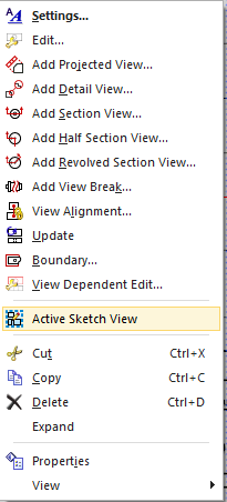
- Right-click the axis frame and select Active Sketch View from the context menu (see figure Abbildung "Active Sketch View").
You create the boundary curve using Studio Spline:![]() :
:
- Insert -> Sketch Curve -> Studio Spline.
- Under Type , select either Through Points or By Poles and select Closed under Parameterization to get a closed curve.

Depending on which method you have chosen, you can define points or poles to create a closed curve that borders the blind hole thread area. If you have defined enough points or poles for the spline, then:
- Finish with OK (see figure "Spline generated").
Creating the breakout
To create a breakout, select Break-Out section![]() , to be found under Insert -> View -> Break-out....
, to be found under Insert -> View -> Break-out....
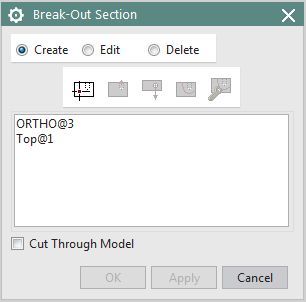
The Break-Out Section window opens (see figure "Breakout Section").
The icons in the navigation bar guide you through the following menu sequences (from left to right: Select View, Indicate Base Point, Indicate Extrusion Vector, Select Curves, Modify Boundary Curves):
| Select the view in which you want to create the breakout. | |
| Define the base point. The base point defines the section plane, it must be specified in any other view. In the basic view, select the circle center. The snap point functions can also be activated here. | |
 Indicate Extrusion Vector: Indicate Extrusion Vector: |
Now it may be necessary to redefine the section plane normal vector. Normally, NX specifies a normal vector. You can use it, or define another one in the vector constructor. The Reverse Vector key can be used to reverse the direction. |
|
Select the boundary curve. You may have to manually switch to the Select Curves mode -> click on the button. |