For this exercise, you need the specification you have just created and the corresponding master model achse_hinten_tpd.

Do not dimension the blind hole thread with Cylindrical  , otherwise a diameter sign will be inserted automatically.
The dimensioning menu appears:
- When subsequently changing dimensions by selecting the dimension - with RMB - and selecting it in the Edit menu.
- By double-clicking on the measurement to be modified.
In this tutorial only controls that are important for you are explained, the rest can be learned by trying it out for yourself.
Enter tolerances
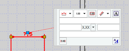
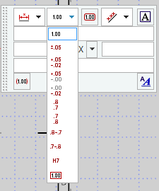
In the dimension menu, you can select whether and how tolerances are to be specified in the dimension text. (see figure "Tolerances")
The X.XX drop-down menu allows you to select the number of decimal places of the measure.
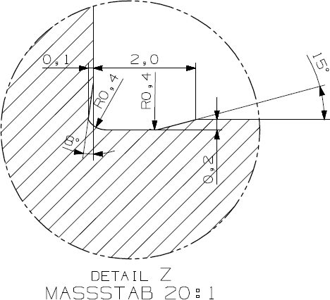
In this exercise, tolerances according to DIN 509 are provided for the undercut. Insert all necessary tolerances according to DIN 509.
Click on the dimensions to be tolerated and open the dimension menu (as described above). You can use the drop-down menu to select the corresponding tolerance specification. If the measurement value is not correct, you can adjust it by double-clicking on the tolerance.
The finished dimensioned detail of the groove can be seen in. (see figure "Groove with tolerances")
Text indications
In addition, you can add and modify the dimension text in the caption fields of the dimension menu.
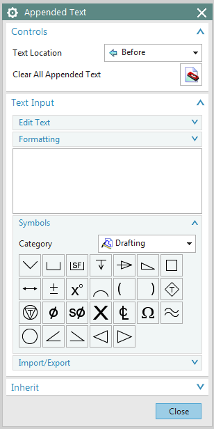
The Edit Appended Text...![]() function is also available in the top right-hand corner of the menu. The text field in which you clicked is always edited.
function is also available in the top right-hand corner of the menu. The text field in which you clicked is always edited.
The arrows in the drop-down menu determine whether the text is positioned in front of or behind (or above or below) the dimension.
The text field for entering the respective dimension text follows.
In the lower part of the Text Editor window, in the Symbols menu, there are some important drawing icons that may be required for dimensioning according to standards. (see figure "Text Editor")
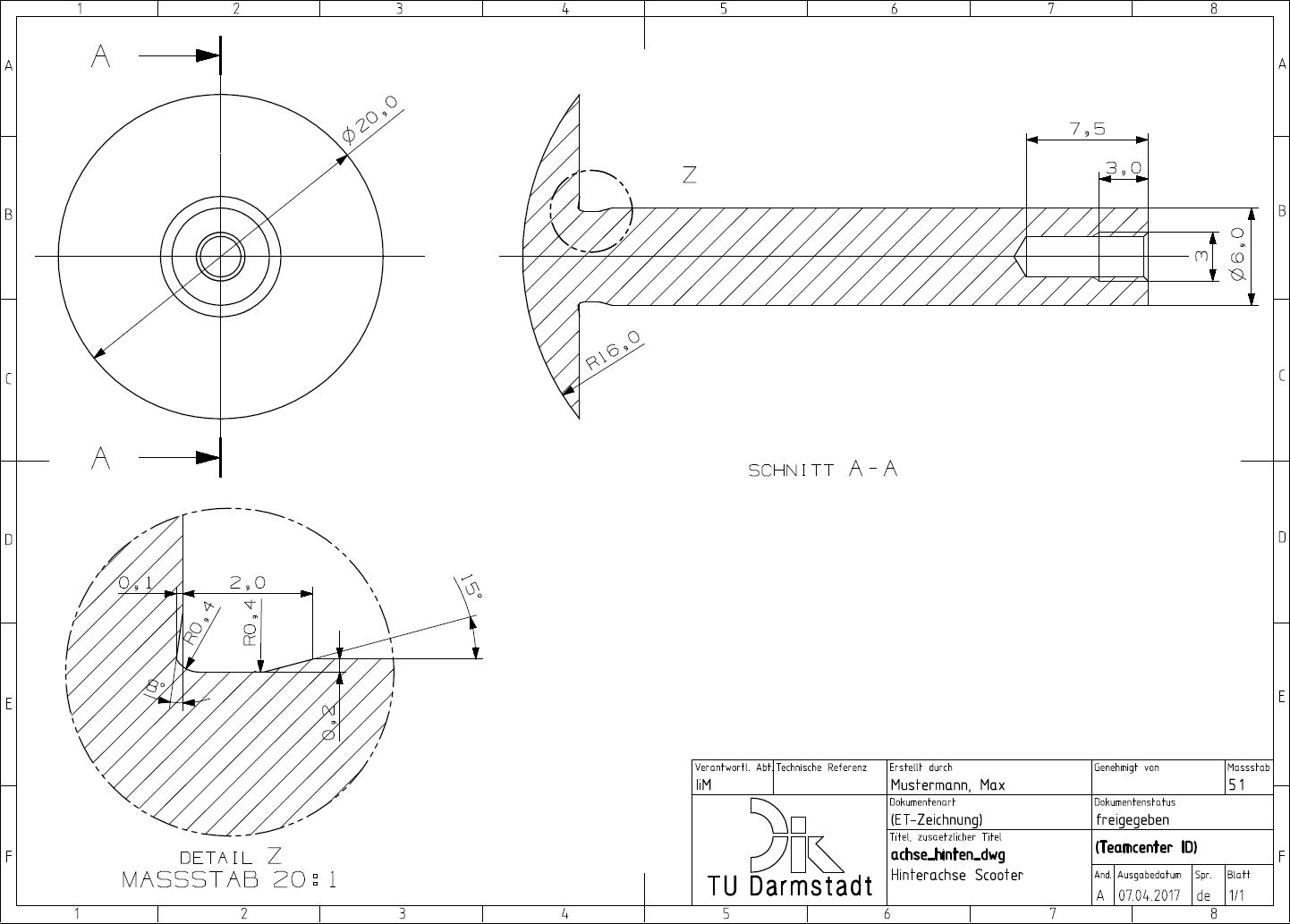
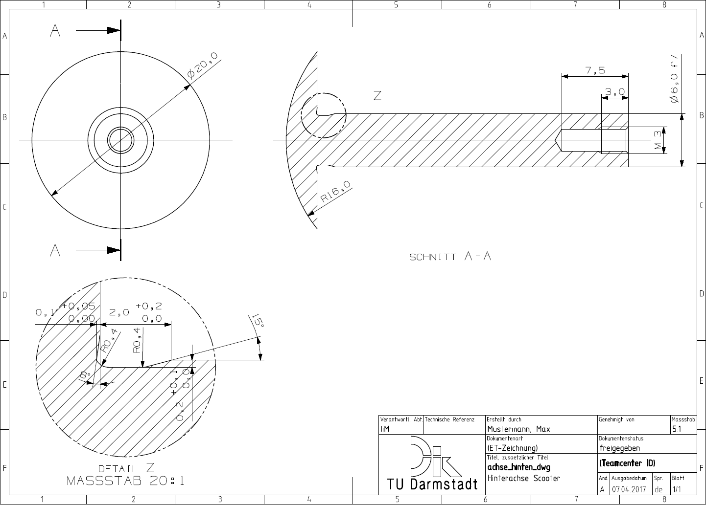
In this drawing you should complete the following text. You can do this by clicking on the size. Insert the following here:- Before the dimension 3 for the thread: M -> M3
- Behind dimension 6 for the diameter of the axis: f7 -> 6 f7
Your drawing should then correspond to the figure (see figure "Dimension text in side view").