You can use the Feature Control Frame function to assign different tolerances to a component.
Overview
In principle, tolerances can be divided into form and position tolerances.
Form tolerances describe the permissible shape deviation that a manufactured workpiece may have from the ideal modelled component. They therefore describe geometric areas within which the tolerated element must lie.
Location tolerances describe the permissible deviation of the real from the ideal position between two or more geometric elements. These are additionally stored in
- Directional tolerances
- Location tolerances and
- Running tolerances.
For more information on the meanings of the various tolerances, refer to chapter 8.4 "Shape and position tolerances" in the script.
| Form tolerances |
 |
 |
| Position tolerances |
| - Directional tolerances: |
 |
 |
| - Location tolerances: |
 |
 |
| - Running tolerances: |
 |
 |
 |
Creating a Tolerance:
Click Feature Control Frame![]() to open the Feature Control Frame dialog box.
to open the Feature Control Frame dialog box.
In the Frame tab, you can set the information to appear in your tolerance frame:
- Under Characteristic you will find a list of the above-mentioned form and position tolerances.
- Under Tolerance you will now find three different boxes:
- First of all, the tolerance range is determined by choosing between diameter
 , sphere diameter
 or square
 .
.
- Next to it you can enter the value of the tolerance range.
- Material requirements can be set in the right-hand box:

minimal material requirements 
maximal material requirements 
Tolerances are independent of the size of the form element
- Under Primary-/Secondary-/Tertiary Datum Reference you can specify reference references to the tolerances that you created with Datum Feature Symbol.
A tolerance frame appears in your graphics window, which may look like this: ![]() . This means that the tolerated face/axis must lie between two surfaces parallel to reference plane A with a distance of 0.1 mm.
. This means that the tolerated face/axis must lie between two surfaces parallel to reference plane A with a distance of 0.1 mm.
Under Associated Objects you can select one or more areas to which your tolerance should refer. These will turn green when you click on the PMI.
Click on Specify Location to place your PMI. To do this, use the LMB to select any element of your component, hold it down and drag the tolerance frame vertically or horizontally to the position in the graphics window on which you want to place your PMI. The PMI is then filed by clicking the LMB again. This should appear automatically in the level of the corresponding view. Otherwise you can select a desired layer under Orientation->Plane. If you have problems with the length of the arrow, you can reduce it under Style->Stub Length. Then confirm with OK.
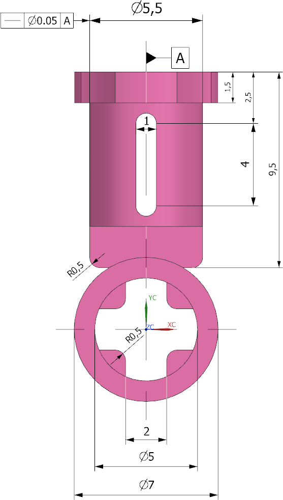
Switch to the Model View "Top" and assign a straightness tolerance to the cylinder with a diameter of 5.5 mm, which specifies that the tolerated axis of the cylinder must be within a cylindrical tolerance zone with a diameter of "0.02 mm" around the axis A.
The result should look like in the following figure (see figure "Top with tolerance")