Using the Surface Finish function, you can create a surface treatment symbol that provides information about the surface quality of your component and the manufacturing processes used.
Roughness parameters:
According to DIN EN ISO 1302, there are three roughness values that provide information about the surface roughness and thus about the deviation from the geometric surface:
- Ra - Arithmetic average roughness value: The arithmetic mean of the absolute values of the profile deviations y from the centerline within the total distance.
- Rz - Averaged roughness: The arithmetic mean of the individual roughness depths of five adjacent individual measuring sections.
- Rmax -Maximum roughness: The largest single roughness depths occurring on the entire measuring section.
More detailed explanations can be found in the lecture notes in chapter 8.3 "Surface finishes".
The surface symbol:
The surface symbol can have different shapes, which provide information about the surface treatment.
| Symbol | Meaning |
 |
Basic symbol; surface is treated, no further requirements for the composition |
| Surface is treated, additional requirements to the condition of the surface are met. | |
 |
Surface is processed during material removal. |
| Surface is processed by material removal, additional information about e. g: Movement, machining allowance,.... | |
 |
Material removal machining is not permitted. |
 |
Material removal machining is not permitted, additionally requirements on the quality of the material. |
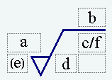
Additional information can be added to complete the icon. These must be arranged as follows:
|
|
a: Roughness value in Ra [mikrometer] b: Manufacturing process, surface treatment c: Separation d: Groove direction e: machining addition f: secondary roughness in Rz or Ry |
More detailed explanations can be found in the lecture notes under chapter 8.3 "Surface finishes" on pages 79 and 80.
Click on Surface Finish![]() to open the Surface Finish dialog box.
to open the Surface Finish dialog box.
- UnderAttributes->Material Removalyou can choose from the surface symbols already explained. The characteristic values are entered in lines (a) - (f) as shown in the figure above.
- UnderAssociated Objects, you can select one or more surfaces to which your interface information should refer. These will turn green when you click on the PMI.
The placement of the PMI on your model works in a similar way to the Feature Control Frame.
Now switch to the view "Lightweight Section #1"and add a surface symbol to the inner surfaces in the right cylinder which says that the surface produced by broaching should have a roughness Ra = 5 .
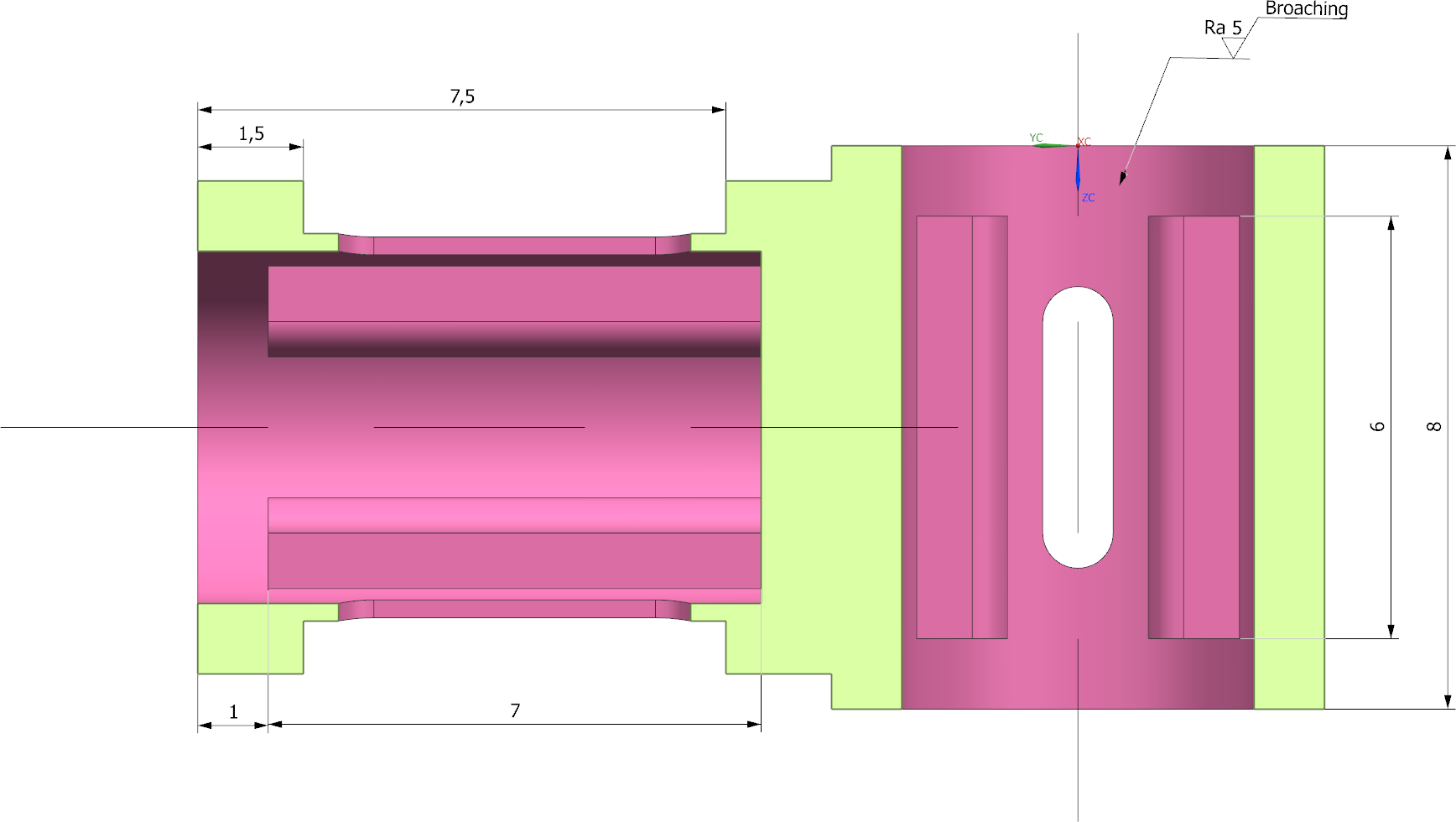
Your result should look like the figure (see figure "Section #1 with R_a").