This exercise deals with the feature Hole ![]() . Using it you can create different types of holes by defining dimension and position.
. Using it you can create different types of holes by defining dimension and position.
Create a new model with the name hole according to the naming convention.
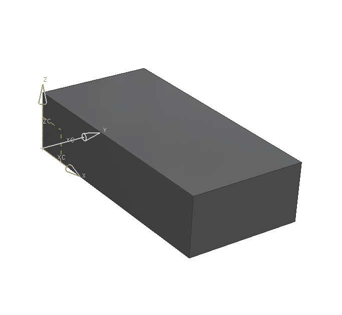
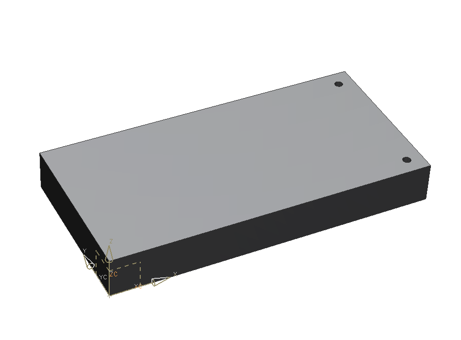
As a basic body you'll need a block with the dimensions: (refer figure "Block")
| Dimension | Value [mm] |
|---|---|
| Length | 400 |
| Width | 200 |
| Height | 50 |
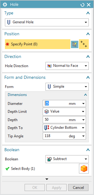
Select the feature Hole ![]() . (refer figure "Menu Hole")
. (refer figure "Menu Hole")
For example you can create the following types:
- General Hole (a standard hole)
- Screw Clearance Hole (a through-body hole, so a threaded screw fits in it)
- Threaded Hole (a hole that has a thread)
With these types you can partially select these different shapes:
Simple hole through or in body ![]()
Counterbored hole ![]()
Countersunk hole ![]()
Cone shaped hole across its whole depth ![]()
| Hint: |
|
Through-body Hole
Select the feature Hole and select simple in the respective drop-down menu ![]() to create a simple through-body hole.
to create a simple through-body hole.
Firstly, select the surface from which your hole should start. At this spot a point will be created, representing the midpoint of your hole. In the menu that pops up subsequently you can change the point's coordinates absolutely. Do NOT do that, since this means your hole is not positioned by parameters (referenced). Confirm this without entering values by clicking Close.
NX now enters sketch mode, in which you can position your hole. Known tools of sketch mode can be used for doing so.
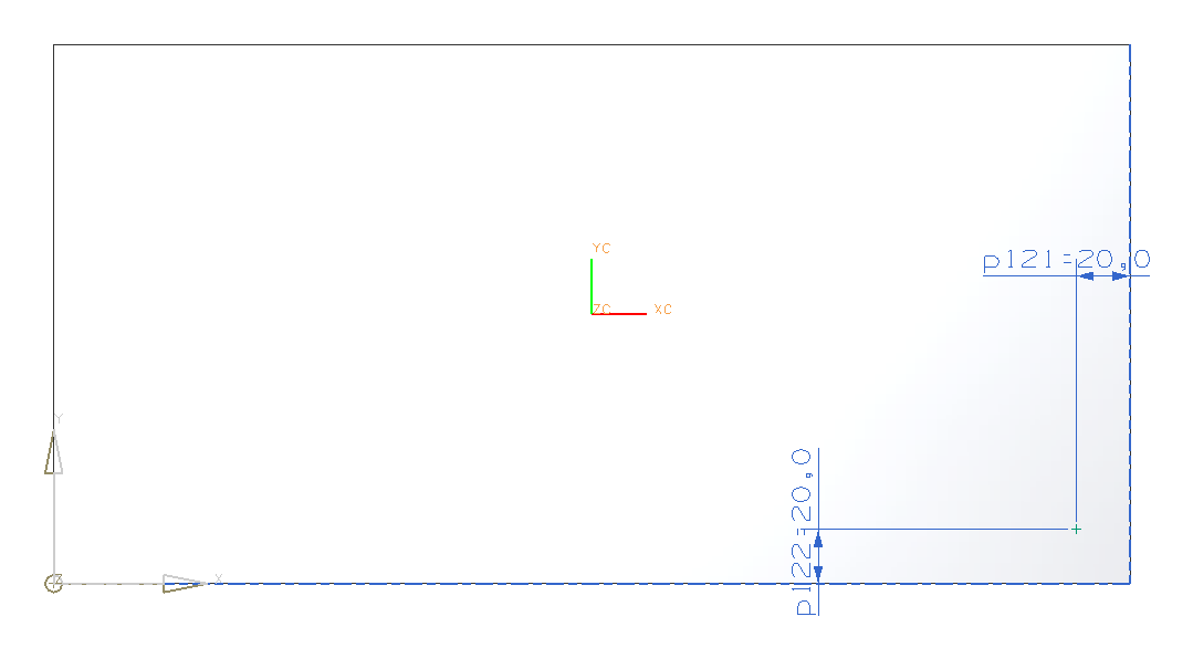
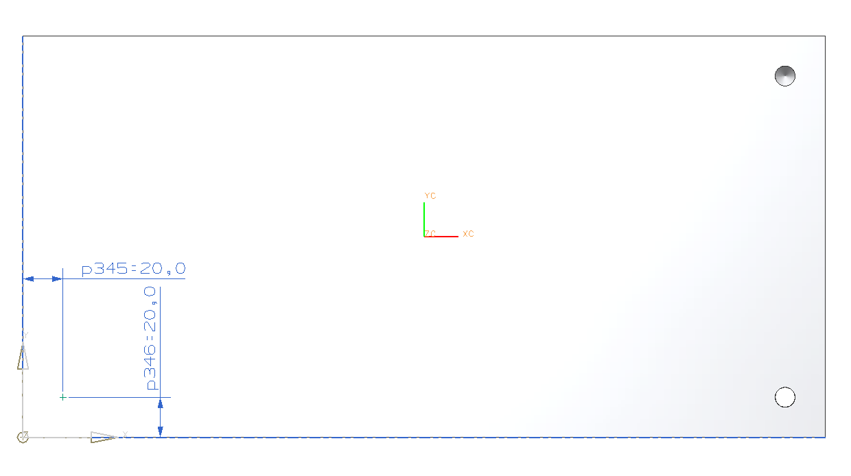
In sketch mode, place the hole in the lower left corner, by clicking ![]() (perpendicular) and selecting a near edge of the block.
(perpendicular) and selecting a near edge of the block.
Enter 20mm as distance. Do the same with the other near edge. The distance is 20mm as well .(refer figure "Positioning through-body hole") End sketch mode via  .
.
Now you can change the diameter of your hole. Set it to 10mm.
There are two different options for creating a through-body hole:
-
 (to a set value)
 (to a surface or plane)
 (until the next change of the volumetric body)
 (through the whole body)
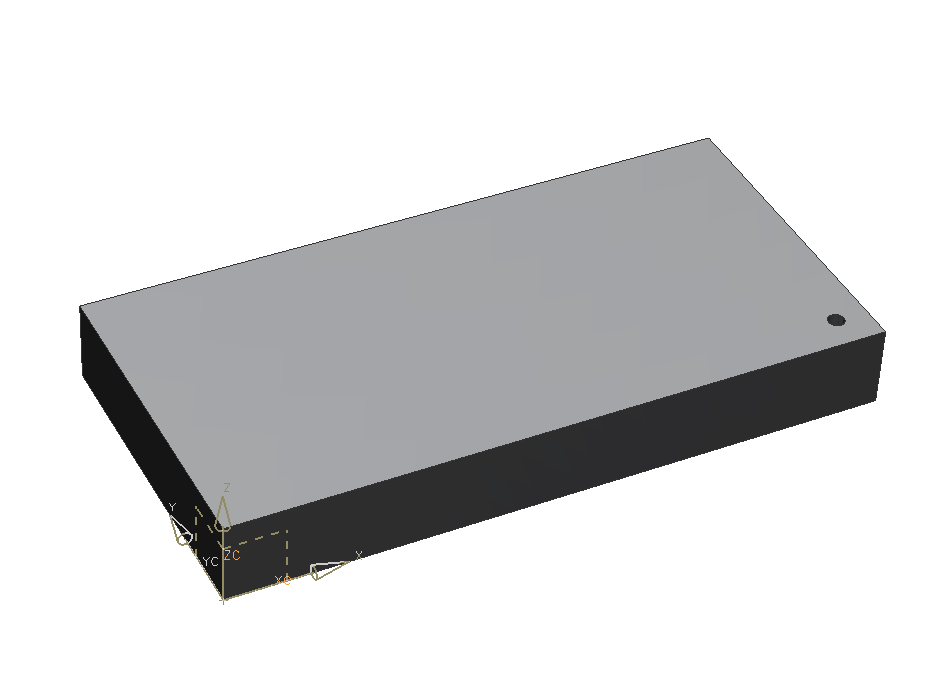
Choose Through Body. Now click OK. (refer figure "through-body hole")
Blind hole (ger. "Sacklochbohrung")
Now create a blind hole. To do so you have to define depth as ![]() .
.
Enter the following dimensions:
| Dimension | Value [mm] |
|---|---|
| Diameter | 10 |
| Depth | 30 |
| Tip Angle | 118 |
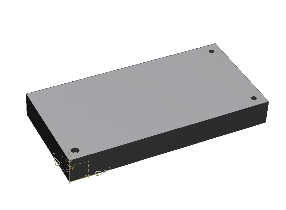
Position the hole in the right corner with a distance of 20mm to the near edges.
The block should now look like in the picture on the right. (refer figure "blind hole")
Counterbored (ger. "Flachsenkung")

Choose  .
.
Enter the following values: (refer figure "Menu Counterbored")
| Dimension | Value [mm] |
|---|---|
| C-Bore Diameter | 14 |
| C-Bore Depth | 10 |
| Hole Diameter | 10 |
| Hole Depth | 30 |
| Tip Angle | 118 |
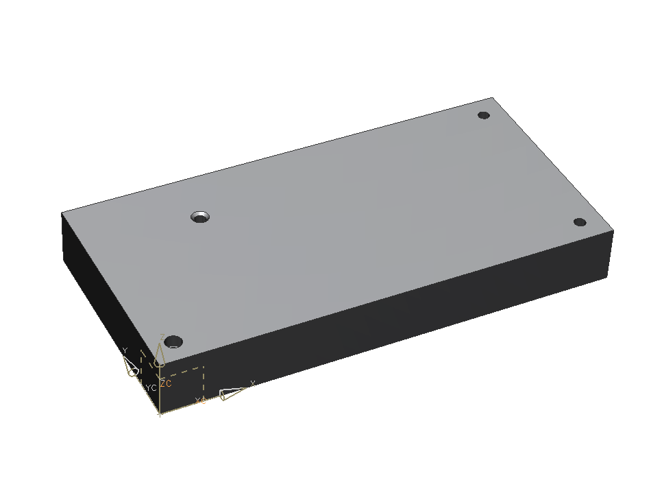
Position the counterbored hole in the left corner as before. (refer figure "Positioning counterbored hole")
The block should now look like in the picuture on the right. (refer figure "counterbored hole")
Countersunk (ger. "Kegelsenkung")
Choose ![]() .
.
Enter the following values:
| Dimension | Value [mm] |
|---|---|
| C-Sink Diameter | 15 |
| C-Sink Angle | 90 |
| Hole Diameter | 10 |
| Hole Depth | 30 |
| Tip Angle | 118 |
The newly created hole should now be placed in the upper corner.
The distances are now 50mm along the short and 100mm along the long edge of the block.
Close this menu with OK. Your screen should now look like in the picture on the right. (refer figure "Holes finished")
| Hint: |
|
Hole on a cylindrical surface
The correct creation and positioning of holes on a cylindrical surface is an advanced technique and is only possible by using datum features.
Create a new model with the name hole_cylinder according to the naming convention.
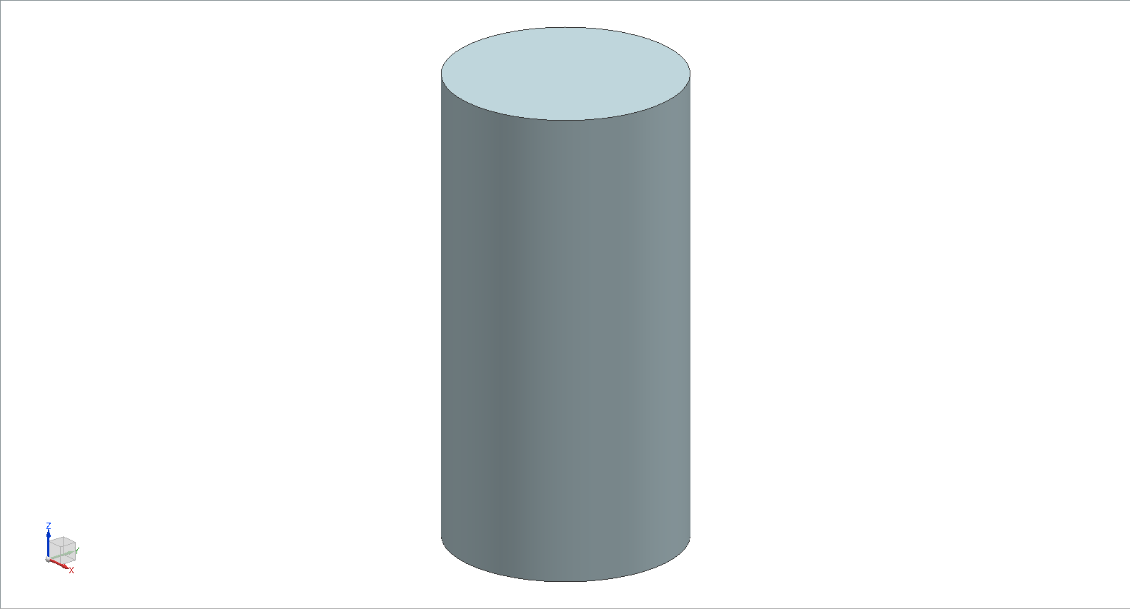
As a basic body you're going to use a cylinder with the following dimensions:
| Dimension | Value [mm] |
|---|---|
| Diameter | 50 |
| Height | 100 |
Make sure that the cylinder is oriented along the Z-Axis. (refer figure "basic body cylinder").
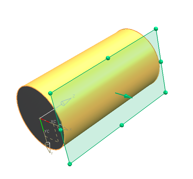
First, create a tangent datum plane on a cylindrical surface:
-
-
- Open the dialog with

- Choose the positioning option

- Click the cylindrical surface
- In "Snap Point" within the symbol bar (refer figure "Snap Point Modes") select the option quadrant point

- Click the quadrant point in positive X-direction.
- Confirm the preview with OK(refer figure "datum plane hole")
- Open the dialog with
-
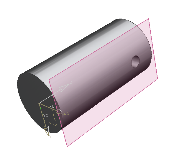
Now you're going to create the hole, a blind hole with diameter 10mm and depth 20mm on the datum plane (click it):
- Distance from the midpoint to the cylinder edge 20mm (click the X-Axis and then the point).
- Midpoint on the Z-Axis (via constraint: Point on Curve). (refer figure "hole cylinder")
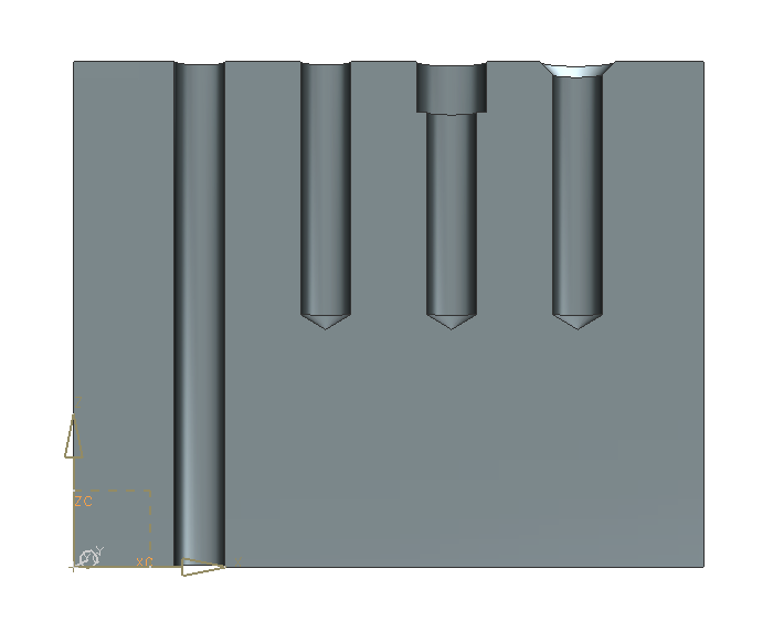
Summary
A through-body hole, a blind hole, a counterbored hole and a countersunk hole have been created. (refer figure "hole examples")
If not stated separately, the standard tip angle of 118 degree is used.
Additionally, holes have been positioned with the function ![]() (perpendicular) within sketch mode.
(perpendicular) within sketch mode.
| Hint: |
|