In this exercise you'll learn about the feature Groove. It is used to create grooves on shafts.
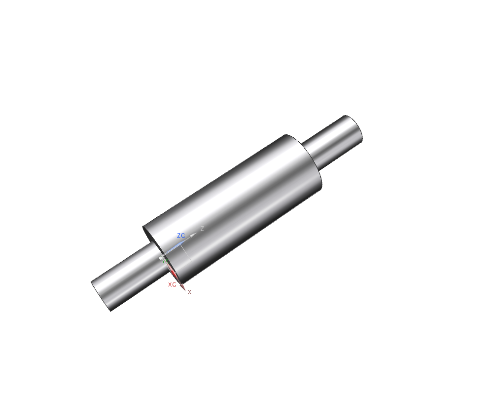
Open the model boss, if you created it previously, and save it as groove according to the naming convention. Otherwise create the model groove and add a cylinder with the following dimensions to it:
| Dimension | Value [mm] |
|---|---|
| Diameter | 20 |
| Height | 50 |
Additionally place two bosses concentrically on the cylinders flat sides:
| Dimenison | Value [mm] |
|---|---|
| Diameter | 10 |
| Height | 20 |
(refer figure "Cylinder with bosses")
Select the feature Groove ![]() .
.
Within Groove, select Rectangular.
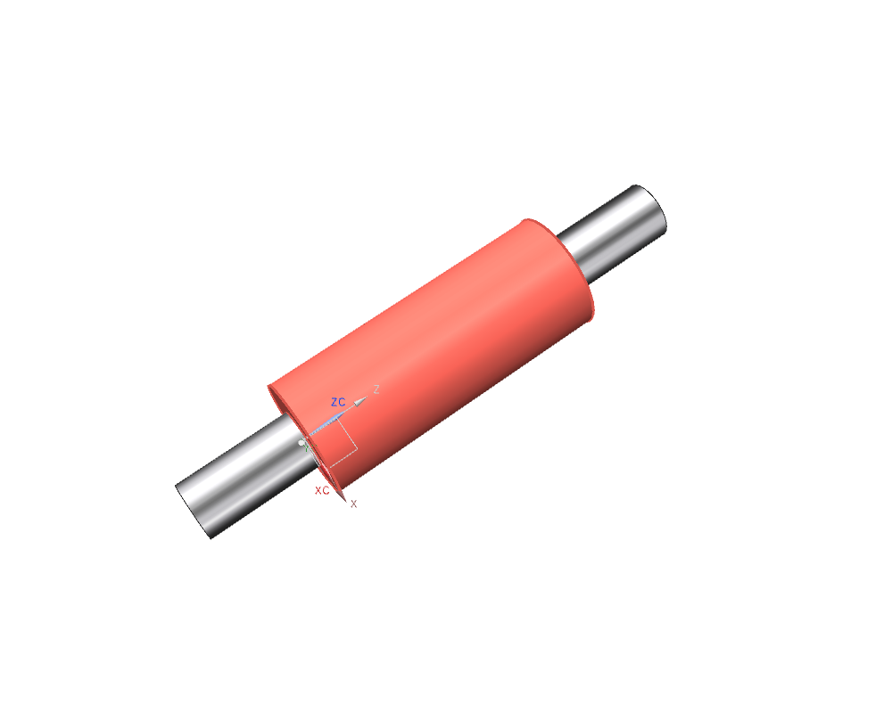
The window Rectangular Groove (refer figure "Menu Rectangular Groove") requires to select a surface for reference. Click the cylinders mantle. (refer figure "Referenced surface")
Then you have to enter the grooves dimensions:
| Dimension | Value [mm] |
|---|---|
| Groove Diameter | 15 |
| Width | 2 |
Confirm with OK.
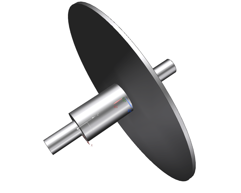
| Hint: |
A disc appears on the screen. It only represents the positioning of the groove. |
You now have to position your groove within the window Position Groove.
First, click the outer edge of the cylinder and then the outer edge of the groove.
The window Create Expression pops up. Enter the value 24mm.
Confirm by clicking OK.
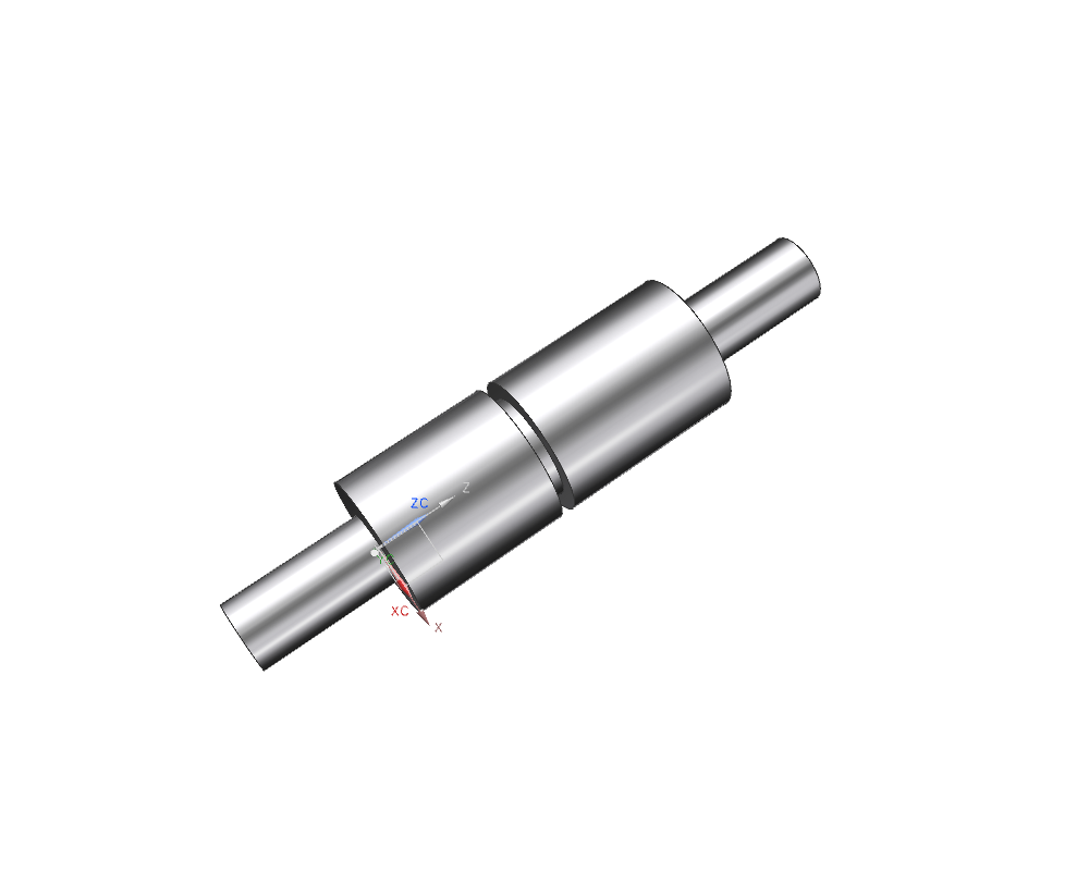
The groove is created subsequently. (refer figure "finished groove")
Create both other types of grooves in random spots:
- Ball End
- U Groove
Similar to the previous explanations.
Enter the following dimensions for the U Groove:
| Dimension | Value [mm] |
|---|---|
| Groove Diameter | 15 |
| Width | 6 |
| Corner Radius | 2.5 |
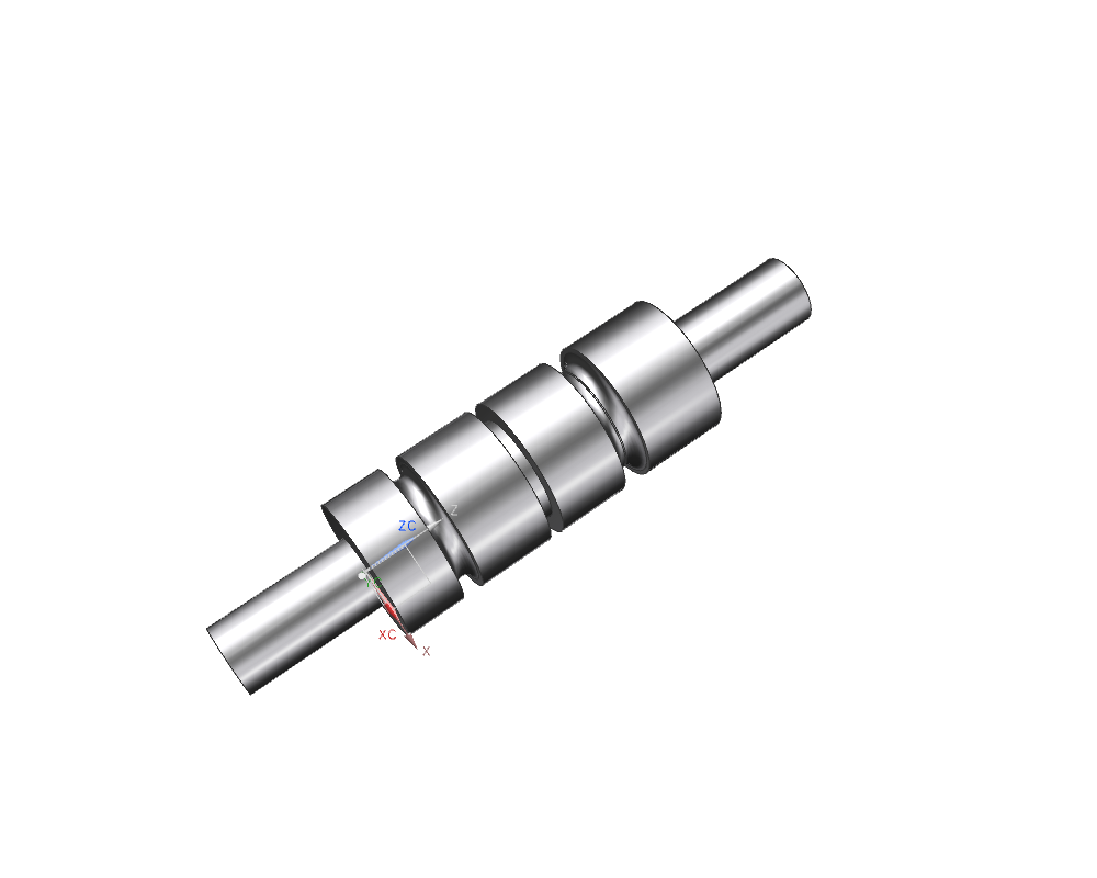
The Feature Groove is especially suited for simple and small grooves on shafts, like grooves for o-ring seals, etc. (refer figure "example for grooves")
| Hint: |
|
This shows the difference between pragmatic modeling in a CAD-system and methods for production. In production sections of a shaft are created by milling down from a cylindric body.