Open the model block, if you previously created it, and save it as pad according to the naming convention. Otherwise, create the model pad with a block with the following dimensions: (refer figure "Block"):
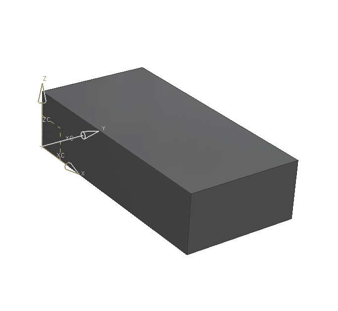
| Dimension | Value [mm] |
|---|---|
| Length | 200 |
| Width | 100 |
| Height | 50 |
Select the feature Pad ![]() .
.
In the window Pad, select the Option Rectangular.
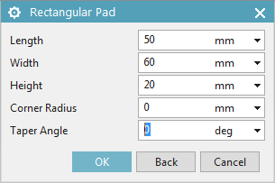
Now the window Rectangular Pad pops up. (refer figure "Menu Rectangular Pad") Next you have to define a surface, on which you want to create the pad. To do so select the surface parallel to the XY-Plane.
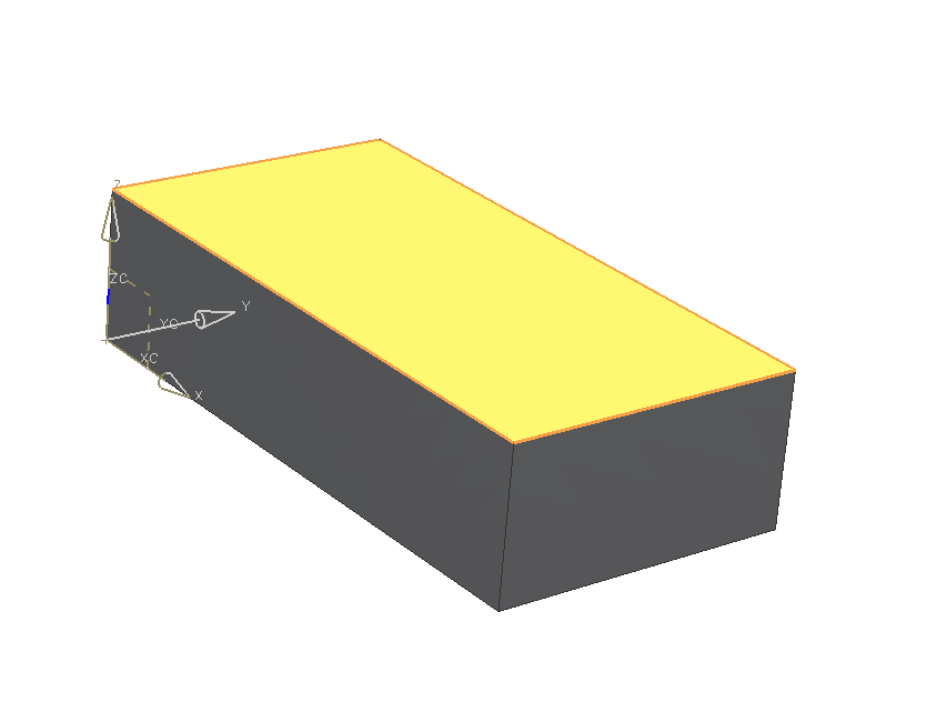
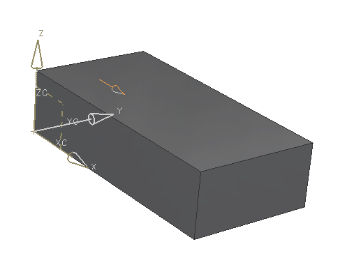
Next, select the XZ-Plane as horizontal reference. (refer figure "referenced surface pad")
Enter the following dimensions into Rectangular Pad:
| Dimension | Value [mm] |
|---|---|
| Length | 50 |
| Width | 60 |
| Height | 20 |
| Hint: |
|
After confirming with OK, the pad appears on the selected surface.
To position your pad, select ![]() (Line onto Line) within the window Positioning and click the edge, that the pad should be positioned at, then click the respective edge of the pad. In this example, the blocks edge in Y-direction should be colinear with the edge of the pad.
(Line onto Line) within the window Positioning and click the edge, that the pad should be positioned at, then click the respective edge of the pad. In this example, the blocks edge in Y-direction should be colinear with the edge of the pad.
Next you have to enter a second reference. The pad should be referenced in Y-direction by setting the distance to the edge of the block in x-direction. To do so select ![]() (parallel at a Distance) Positioning. Then click the edge of the block in x-direction and subsequently the respective edge of the pad.
(parallel at a Distance) Positioning. Then click the edge of the block in x-direction and subsequently the respective edge of the pad.
The window Create Expression pops up. Enter 10mm and confirm by clicking OK.
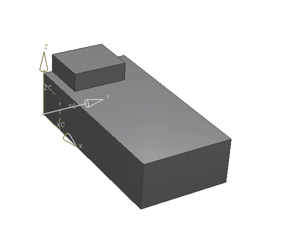
The pad appears in the specified position on the block.
Close this menu by clicking Cancel.