You will now learn how to change the line representation in a technical drawing.
Changing the Line Display
In this window, you can define presettings or make changes regarding the line representations in views. There is one menu item for setting each of them:
- Hidden Lines
- Visible Lines
- Smooth Edges
- Virtual Intersections
To make it clear that the hole is a clearance hole, this section will include hidden edges in the side view of the spacer.
- Click on the Hidden Lines menu item in the Settings menu..
- Set the first pull-down menu from to -------- and the second from Original to ——— 0.13 mm mm.
- Confirm with OK.
| Note: |
|
You can insert the still missing centerline in the side view under Insert -> Centerline -> 2D Centerline by selecting By Points in the corresponding dialog at the top of the dialog box and selecting the center of the leftmost and then of the rightmost vertical lines of the spacer in the side view and confirm with OK.
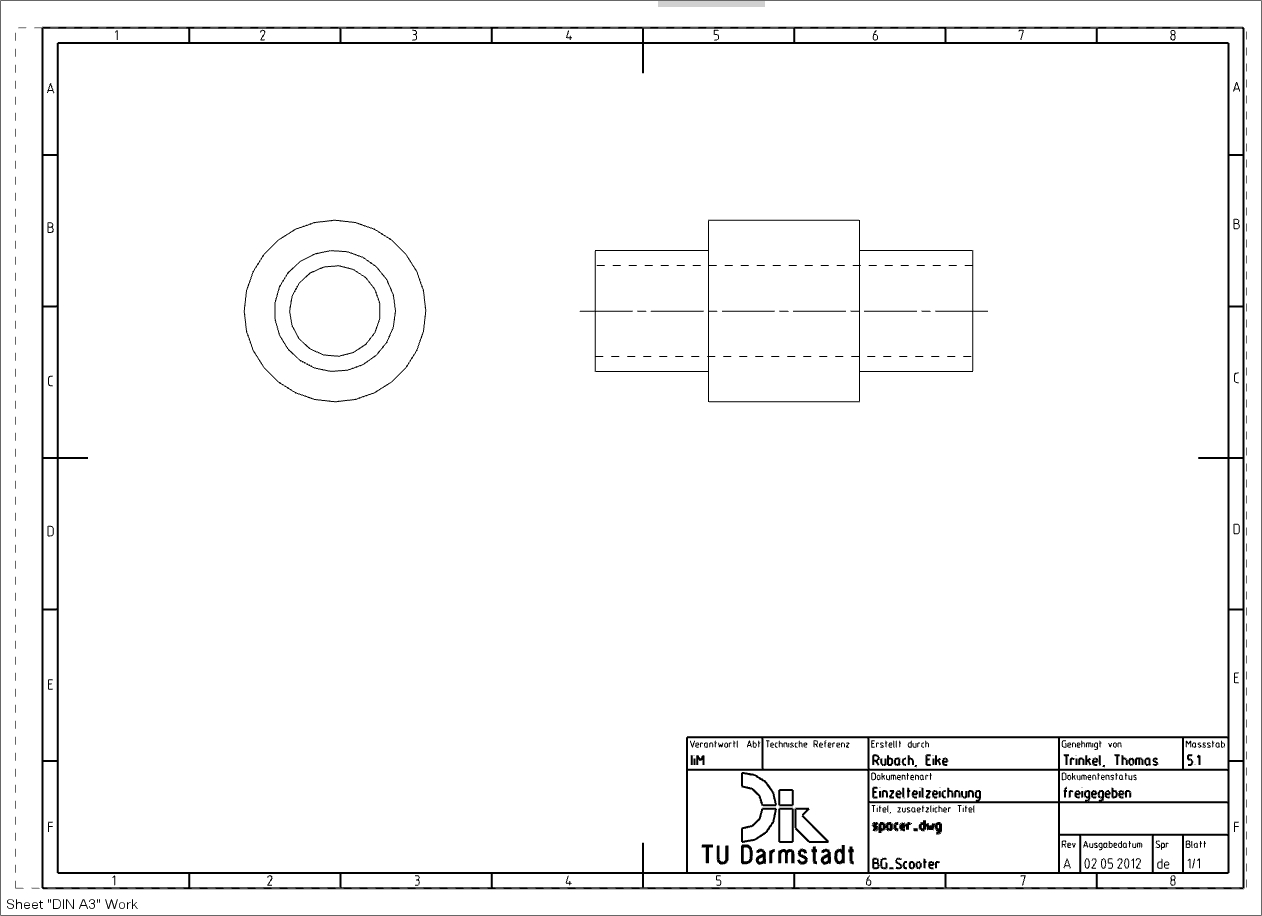
The drawing should now correspond to the illustration (see figure "Hidden Lines").
| Note: |
|
Hide sketches, axes, planes and frames:
- For sketches, axes and planes, proceed as follows: Switch from Drafting-Mode to Modeling-Mode. Open the window Class Selection via Edit -> Show and Hide -> Hide... Select the different categories (several selections with pressed STRG-key), confirm with OK and click on the button Select All. Confirm with OK.
- To hide the frames on the individual views, switch back to drafting mode. Choose Preferences -> Drafting..., switch to the View tab and deactivate Display Borders. Confirm with OK.
The tutorials, the basics (e. g. NormInfo) and the lecture notes provide information and suggestions for the derivation of individual part drawings.