Overview
Overview of the dimensioning options in the Linear![]() and Radial
and Radial![]() menus:
menus:
| Icon | Function | Label | To be found under: |
|---|---|---|---|
| Horizontal dimensioning | Horizontal | Linear |
|
| Vertical dimensioning |
Vertical | Linear |
|
| Parallel dimensioning | Point to Point | Linear |
|
| Orthogonal dimensioning | Perpendicular | Linear |
|
| Cylindrical dimensioning |
Cylindrical | Linear |
|
| Diameter dimensioning |
Diameter | Radial |
|
| Standard radius dimensioning | Radius | Radial |
Further standard dimension icons are listed separately in the menu bar:
| Icon | Function | Label |
|---|---|---|
 |
Chamfer dimensioning |
Chamfer |
| Angular dimensioning | Angular | |
 |
Circular thickness dimensioning |
Thickness |
| Arc length dimensioning | Arc Length | |
| Coordinate dimensioning | Ordinate Dimensions |
It is a good idea to use these standard dimension icons, as they eliminate the need to insert special characters afterwards.
Standardized dimensioning
The following dimension types are distinguished for standardized dimensioning:
| Parallel dimensioning | This is a reference dimension. It is often used when the components to be manufactured are machined with lathes and/or milling machines. Several dimension lines are entered parallel to each other for linear dimensions and concentric for angular dimensions. |
| Chain dimensioning | The individual dimensions are lined up directly next to each other. It should only be used if this is necessary for production. Otherwise, there is too great a risk that the tolerances of the individual sections or the tolerance of the total length may not be adhered to. The reason: Each individual dimension has its own tolerance. The deviations add up in the unfavorable case, which results in a greater deviation of the total length. |
| Progressive dimensioning |
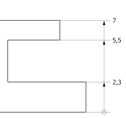
The increasing dimensioning is a reference dimensioning, in which each form element is progressively dimensioned from a reference element. The dimension lines are usually arranged in a superimposed row starting from the origin. |
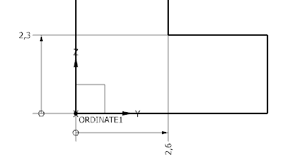
| Coordinate dimensioning | This is a reference dimension in a coordinate system. It is mostly used for the drawings of components that are machined with programmable machines (CNC machines). |
The different dimension types can also be used in combination if it increases the information content of the drawing.
| Icon | Function | Label |
|---|---|---|
| Chain dimensioning |
Chain | |
| Parallel dimensioning (dimensioning via reference edges) | Baseline |
Coordinate dimensioning and progressive dimensioning can be performed using the Ordinate![]() function.
function.
Dimensioning for production
When drawing and dimensioning, you should always consider how the part to be displayed will be manufactured later and dimension it accordingly. Therefore, make sure that your component is already in the manufacturing position.
We now begin with the dimensioning of the spacer.
Cylindrical dimensioning
Now you have to dimension the shaft section of the spacer.
Open Linear![]() and set the method Cylindrical
and set the method Cylindrical in the Measurement field.
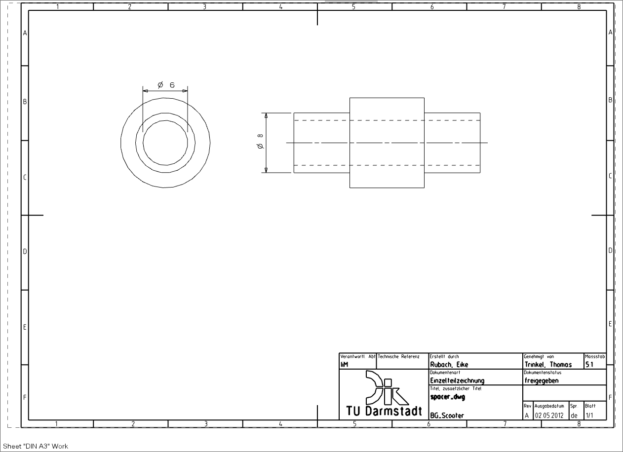
Cylindrical (diameter dimensioning) offers the advantage that you do not have to insert the diameter symbol afterwards.
- Click the parallel horizontal boundary lines of the shaft one after the other in the side view with the LMB.
- Move the dimension that now appears to a suitable position.
- Confirm it with the LMB (see figure "Shaft dimensioning").
Diameter dimensioning
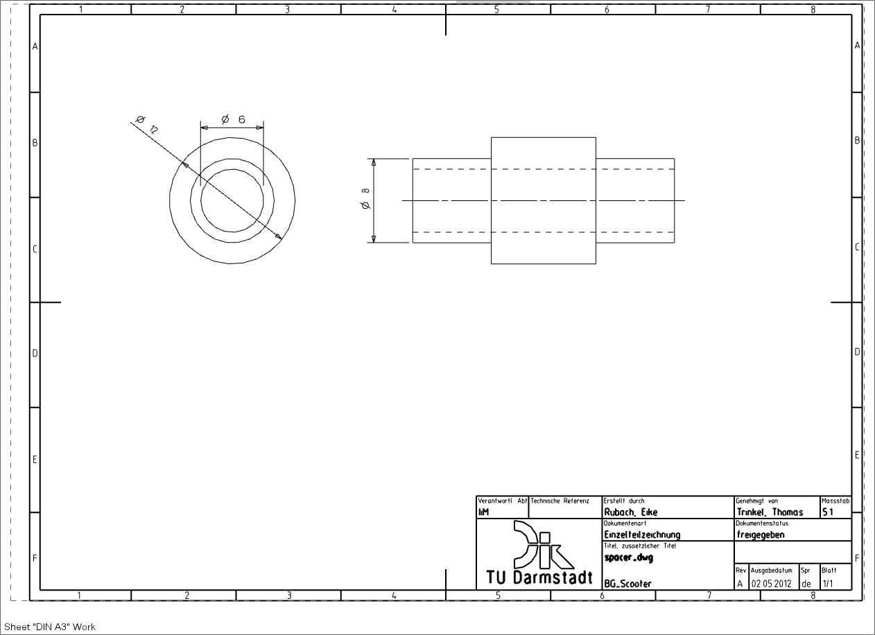
Another way to dimension the diameter of the spacer is to specify the diameter in the basic view. Go to Radial ![]() and select Diametral
and select Diametral![]() in the field "Method".
in the field "Method".
- Click on the outer circle in the basic view with the LMB.
- Move the dimension that now appears to a suitable position.
- Confirm it with the LMB (see figure "Diameter dimensioning").
| Attention: |
|
Length dimensioning
In NX there are several ways to insert linear dimensions in drawings.
In this section, you will learn three different types length dimensions required for the Spacer.
The positioning of the dimensioning is identical for all types of linear dimensioning. They only differ in the order in which they are selected.
Positioning:

- Horizontal dimensioning

Open Linear and set the "Method" in the Measurement field to Horizontal.
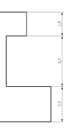
To dimension the length of a horizontal line, you must click on a line as a reference element. (see figure "Horizontal dimensioning")
The same procedure applies to vertical dimensions.
- Perpendicular length dimensioning
Another possibility to carry out a length dimensioning is perpendicular distance dimensioning. Use this to measure the overall length of the spacer.
Open Linear
and set the "Method" Perpendicular  , to open perpendicular distance dimensioning. First, select a vertical boundary line of the total distance. A second reference point is then selected as the second reference.
You should note which snap functions are activated and possibly activate other functions, such as line end point or intersection point.
- Automatic dimensioning (Rapid Dimension)

With automatic dimensioning, you can freely select reference elements. You can click either a horizontal line or a vertical border and a fiducial or two fiducials.
You can also move the dimension to vertical, horizontal or inclined direction to obtain different dimension types and select the appropriate (LMB) type. If the desired dimension is not included, you can abort the procedure with the middle mouse button.
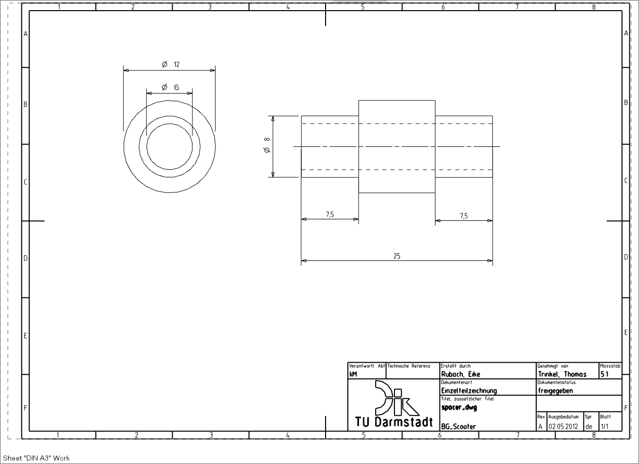
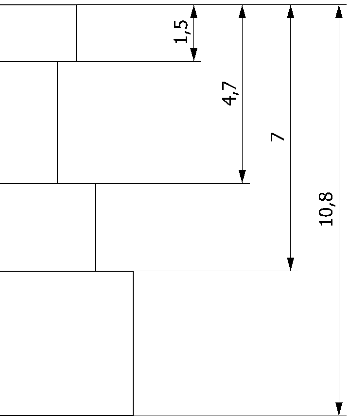
Your drawing should look like the illustration at the end of the exercise (see figure "Finished Dimensioning").
| Note: |
|