Frame and interface
![]() Frames hierarchically group any other material and information flow objects. They are used reduce the complexity of your your simulation models. Each frame represents a small part of your complete simulation model. Frames can also contain one or more subframes.
Frames hierarchically group any other material and information flow objects. They are used reduce the complexity of your your simulation models. Each frame represents a small part of your complete simulation model. Frames can also contain one or more subframes.
For the input and output of objects Tecnomatix Plant Simulation provides the ![]() Interface element. Interfaces are either in- or outputs. Using the connector you can connect objects to a frame. Every time you connect a connector to an interfaced frame a dialogue opens to specify the connection (see figure 1). Unconnected interfaces are marked with a red symbol
Interface element. Interfaces are either in- or outputs. Using the connector you can connect objects to a frame. Every time you connect a connector to an interfaced frame a dialogue opens to specify the connection (see figure 1). Unconnected interfaces are marked with a red symbol ![]() .
.
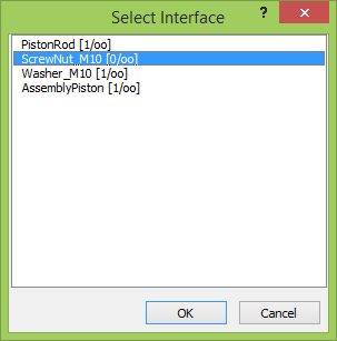
Figure 1: Select interface
Enhance your simulation model
Task:
Create the following subframes and the corresponding interfaces:
- Manufacturing of in-house goods
- Name: Manufacturing
- Input interfaces: HousingCover, PistonRod, Worker
- Output interfaces: Interface
- Assembly of the housing cover
- Name: PreAssembly_HousingCover
- Input interfaces: HousingCover, PlainBearing, DirtDeflector
- Output interfaces: Assembly_HousingCover
- Assembly of the piston rod
- Name: PreAssembl_PistonRod
- Input interfaces: PistonRod, ScrewNut_M10, Washer_M10, Assembly_Piston, Worker
- Output interfaces: Interface
Connect the following sources to the interfaces:
- HousingCover > Manufacturing.HousingCover
- PistonRod > Manufacturing.PistonRod
- PlainBearing > PreAssembly_HousingCover.PlainBearing
- DirtDeflector > PreAssembly_HousingCover.DirtDeflector
- ScrewNut_M10 > PreAssembly_PistonRod.ScrewNut_M10
- Washer_M10 > PreAssembly_PistonRod.Washer_M10
- Assembly_Piston > PreAssembly_PistonRod.Assembly_Piston
Try to adjust the input and output position of each interface at the frame:
- Inputs are arranged at the left side of the frame,
- Output are arranged at the right side of the frame, and
- Workes are arranged at the bottom side of the frame.
Step-by-Step:
-
Create three frames on your simulation model using the toolbox icon for frame
 .
. - Open each frame and create inside the desired amount of interfaces (in- and output).
- Open each interface and input the desired name for example "Worker" (see figure 2).
- Select side position for example bottom (see figure 2).
- Using the tabs at the bottom of your simulation model you can return to your main simulation model, called "Frame".
- Connect the sources to the appropriate frames by clicking on the connector symbol in your toolbox, then on the source object and finally on the frame.
- A dialogue (see figure 1) opens to select the interface. Chose the right interface for your source and submit with the button "OK".
- Repeat for all frames and all interfaces.
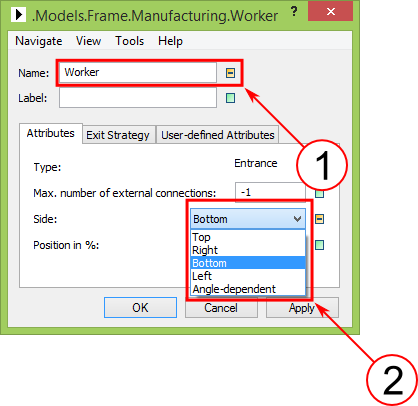
Figure 2: Side of interfaces at frame icon