Graphical user interface
Tenomatix Plant Simulation’s graphical user interface consist of different sections. Each section can be customized in form and position:
- Menu of Tecnomatix Plant Simulation,
- Class library with all available class elements,
- Toolbox with shortcut symbols,
- Simulation network, and
- Console for status messages.
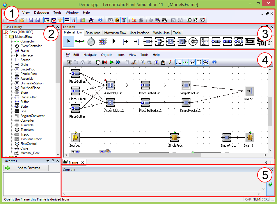
Figure 1: Overview of the graphical user interface of Tecnomatix Plant Simulation
All selected classes are listed in the class library. Objects are instantiated using the predefined values in this class library. You can open, duplicate and derive each class element by right-clicking a class element (see figure 1)(1). You can then change the default parameters.
Duplicating an element copies all default parameters to a new class element. Both elements exists independent from each other. In comparison a derived class elements links all default parameters to its parent (2). Changes made within the parents are directly transferred to the derived element as long as an attribute is not overwritten by the derived class element (3). To overwrite attributes you must explicit mark them by clicking on the icon next to the attribute. Otherwise the attribute is read-only.
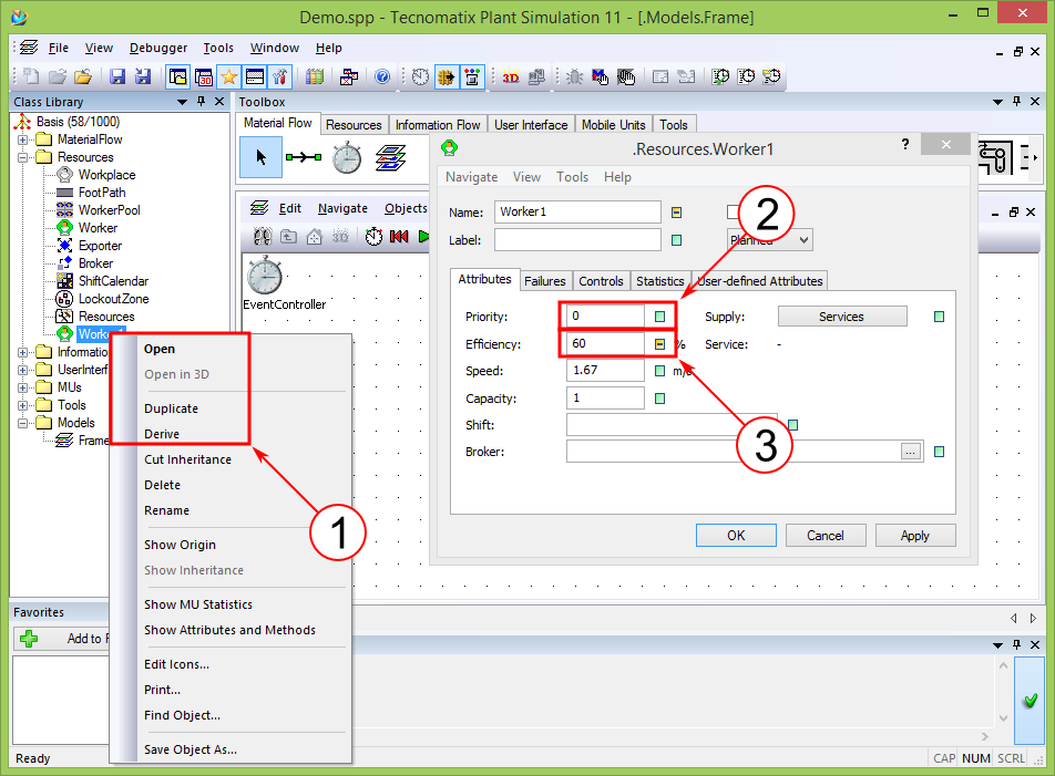
Figure 2: Edit parameter of class element
In the simulation network you have multiple tabs at the bottom. Each tab shows a part of the simulation model. Mostly a tab shows a part of your simulation network, called frame. Frames are hierarchical connect. There is always at least one main frame. Sub frames are optional. They are used to divide your simulation problem into sub simulations. The main frame as well as your sub frames can be found at to bottom of your class library in the sub node “Models”.
Tecnomatix Plant Simulation uses pictographs to visualize simulation’s elements, intermediate stats and results. Your main frame normally contains the “Event Controller”. This is the element for controlling the start time, stop time and speed of your simulation. Additional elements can be inserted to your network either by drag-and-drop from the class library or left-clicking the icon in the toolbox and left-clicking again in your frame. Holding the “CTRL” key on your keyboard allows you to insert multiple of the selected elements.
Notice: On inserting class elements to your network, they are instantiated. Thus you insert object with concrete values. But editing the class elements will still alter the objects in your network.
In case you need any assistance you can also use the Tecnomatix Plant Simulation help file. At any time press “F1” on your keyboard to open context sensitive help topics. Alternativ you can choose the menu entry “Help > Contents” to get the general help. More example are found on program start-up. In the window you can choose the link “Getting started > Examples/Infos”.