Worker, workplace, worker pool and foot path
For the simulation of human resources Tecnomatix Plant Simulation provides the  worker class element. Workers can perform different task (Services) when they are ordered to a machine such as repairing or transporting goods. They have different attributes such as efficiency or speed which control further their behavior.
Worker can either perform task remotely or directly at the machine. Therefore ![]() workplaces have to be linked to a specific machine. Each provides specific services.
workplaces have to be linked to a specific machine. Each provides specific services.
Workplaces are connected to the  worker pool where all workers are created as well as return during break or change of shift.
The worker pool and the workplace are connected using the ![]() foot path element.
foot path element.
Enhance your simulation model
Task:
Add the following worker to the worker pool:
- Manufacturer
- Name: Manufactuer
- Derived from "Worker"
- Quantity: 1
- Supported Services: derived from worker, not overwritten
- Overwritten symbols for states "Operational" and "working":

- Assembler
- Name: Assembler
- Derived from "Worker"
- Quantity: 1
- Supported Services: Assembler
- Overwritten symbols for states "Operational" and "working":

Create the workplaces:
- Every station in the in-house production (Manufacturing) needs its own workplace.
- The assembly station in the pre-assembly of the piston rod needs its own workplace.
- The assembly station in the frame needs its own workplace.
- A worker pool is needed in the frame which is connected to all workplaces.
Create the foot paths to the workplaces.
Notice: A connector in the Manufacturing frame between washing and measurement is no longer needed.
Step-by-Step:
- Right-click on the class element "Worker" and select the menu entry "Derive".
- Open the class element "Worker1" and edit the name and the attribute "Supported Services". Submit by pressing the button "OK".
- Right-click on the created class element and select "Edit icons...".
- Change the icons for the states "Operational" and "working".
- Repeat for the second worker.
- Open the Manufacturing frame.
- Place workplaces next to the single processing stations.
- Open every workplace and check that the desired station is filled in the field "station" (see figure 1) (1).
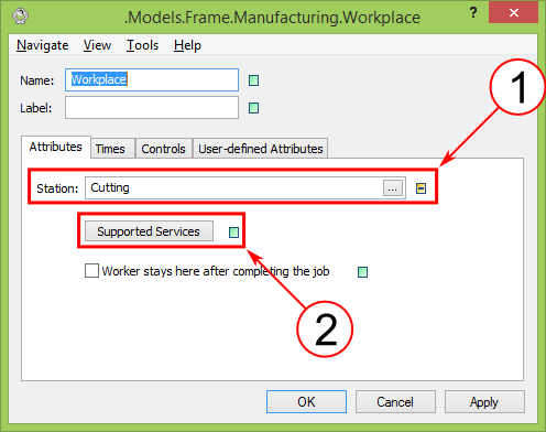
Figure 1: Workplace
- Edit the class element for workplaces. Open it, left-click on the button "Supported Services" and insert "StandardService" (2) (see figure 1).
- Connect the workplaces in the Manufacturing frame with footpath, connectors and the interface "Worker". In this example the length of the foot path is not relevant (see figure 2). Therefore select the
 footpath from the toolbox. Click twice on the frame und finish the creation by pressing the button "Finish" of the dialgoue.
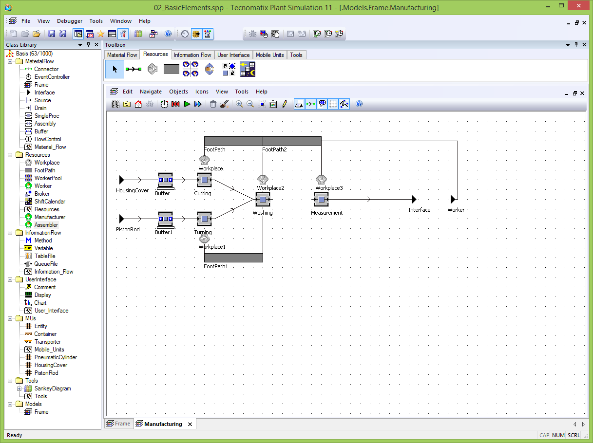
Figure 2: Intermediate simulation model for Manufacturing frame
- Equally proceed with the PreAssembly_PistonRod frame (see figure 3).
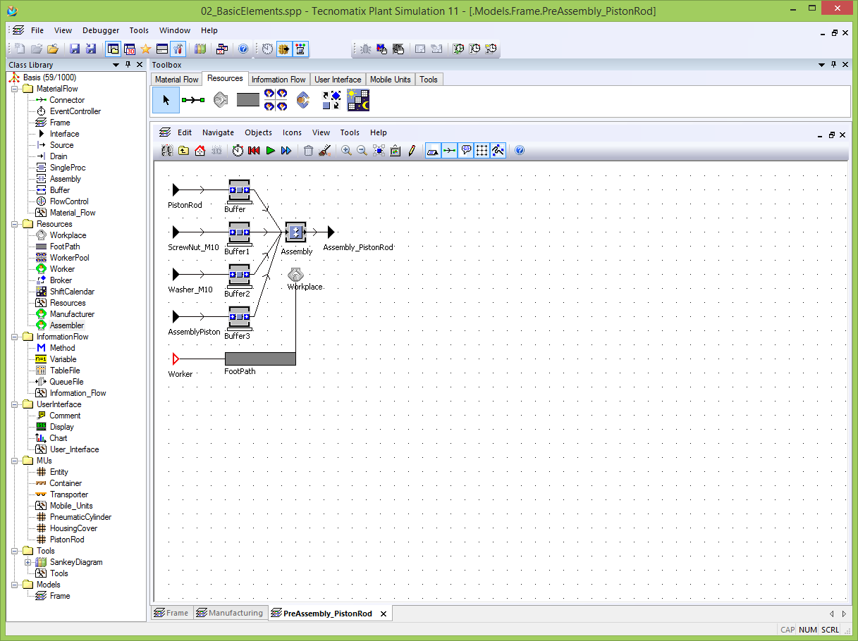
Figure 3: Intermediate model for PreAssembly_PistonRod
- In the main frame place a workplace near the assembly station and open it. Change the Supported Services to "Assembler" so that only the worker "Assembler" can perform the tasks (2) (see figure 1).
- Add a worker pool to the main frame and connect the pool with the sub frame and the workerplace using connectors and foot paths (see figure 4).
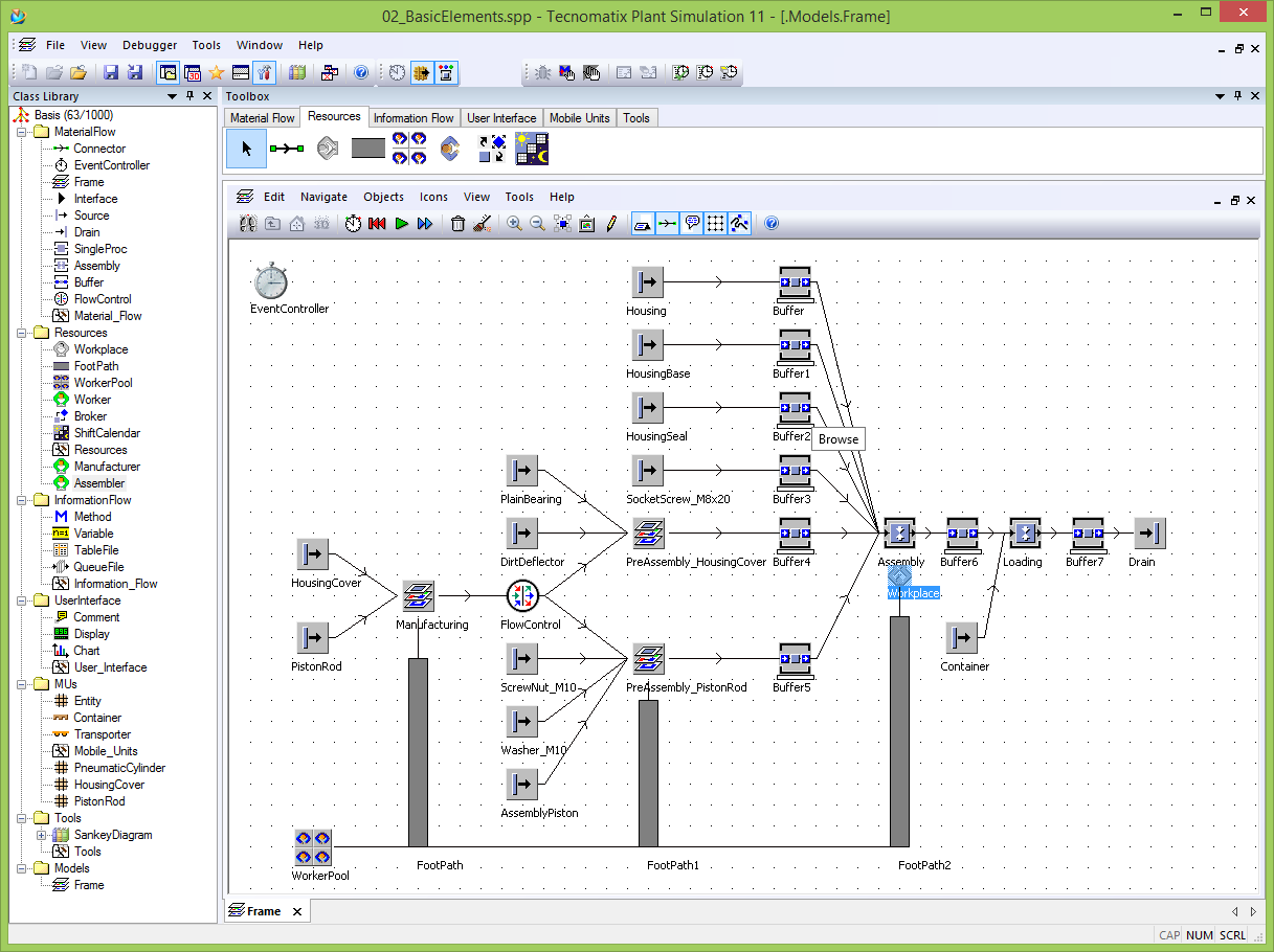
Figure 4: Intermediate simulation model
- Drag and drop one workers "Manufacturer" and one workers "Assembler" on the "WorkerPool". Alternativ open the WorkerPool and edit the "Create Table".In summary 3 workers are created (1x Worker, 1x Manufacturer, 1x Assembler).