2.1.3 Tree Structure
The Process Designer interface is similar to Windows applications. This means that you must first select the object(s) that you want to work on in order to activate the required options. Objects can be selected either in one of the Trees or in the Graphic Viewer. The options are accessible through menus, toolbars, and context menus.
Navigation Tree
The Navigation Tree is the main element of Process Designer where you place your project structure and navigate through objects within the project. The Navigation Tree contains the project root node and all sub folder structure of the objects stored in the project. This is significantly similar to the construction of a Windows application structure. This means that you can click on the "+" and "-" symbol to open and close the sub folder.
By default, only one Navigation Tree is displayed. You can browse other objects in a new Navigation Tree by following one of these steps:
- Right-click the object node and select Navigation Tree from the context menu.
- Click the object node and select View > Open With > Navigation Tree from the menu bar.
To add a new object in a project from the Navigation Tree:
- Click the Project Root Node in the Navigation Tree.
- Right-click and select New from the context menu.
- A New dialog box with a list of all available objects opens. Select a desired object type and click OK.
From the Navigation Tree you can also view the properties of the project.
- Click the Project Root Node in the Navigation Tree.
- Right-click and select Properties from the context menu.
- A Properties window of the project opens.
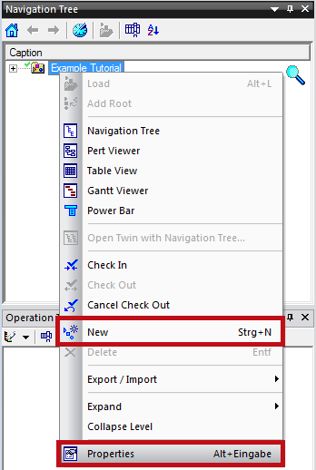
Figure: New and Properties Command from Right-Click Context Menu
Operation Tree
The Operation Tree displays all object types Operation and the hierarchy of operations required to perform the work tasks to build a product. The top level of this hierarchy or the operation root node defines the work tasks in its most general terms, for example "Assembly a Product". The hierarchy then branches downward into a series of first-level manufacturing operations, which in turns include their sub operations in the next hierarchy level. The operation root node is divided in detailed sub operations until the work task is fully expanded and every operation is included.
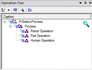
Figure: Example of Operation Tree
Product and Resource Tree
The Product Tree displays all object types Parts and the hierarchy of a product with all its parts which are currently loaded. Similar to the Product Tree, the Resource Tree displays all object types Resources which are currently loaded. The Resource Tree contains a top-down, hierarchical view of all of the resources that are used to manufacture a product, from the entire plant down to individual tools and fixtures. The currently active resource is displayed with a light blue box around it. Any new resources added to the engineering data by dragging and dropping from the Navigation Tree are automatically added as children to this resource.
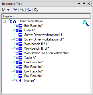
Figure: Example of Resource Tree
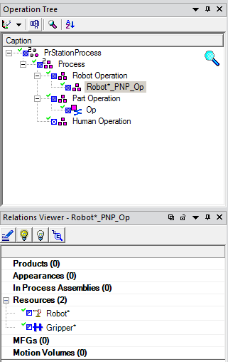
Relations Viewer
The Relations Viewer enables you to view and manage relations between objects. For example, if you click any operation from the Operation Tree, the Relations Viewer shows which Parts, Resources, and Manufacturing Features (Mfgs) are assigned to this operation. The Relations Viewer is synchronized with other viewers and displays all changes as they occur. If you delete an object from the Relations Viewer, its relationship with the root object will also be deleted.